


Chapter 2 Installation and Wiring|VFD-S Series
2-22 Revision August 2006, SE08, SW V2.61
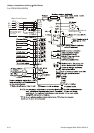
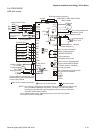
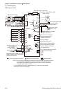
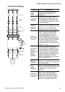
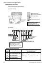
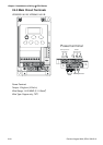
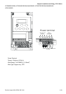
2.4.3 Main Terminals Connections
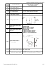
Terminal Symbol Explanation of Terminal Function
R/L1, S/L2, T/L3 AC line input terminals (3-phase)
L/L1, N/L2 AC line input terminals (1-phase)
U/T1, V/T2, W/T3
AC drive output terminals for connecting 3-phase
induction motor
+2/B1, B2 Connections for Brake resistor (optional)
+2/B1, +1 Connections for DC Link Reactor (optional)
Earth connection, please comply with local regulations.
Mains power terminals (R/L1, S/L2, T/L3 and L/L1, N/L2)
Connect these terminals via a non-fuse breaker or earth leakage breaker to 3-phase AC
power (some models to 1-phase AC power) for circuit protection. It is unnecessary to
consider phase-sequence.
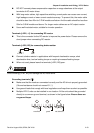
It is recommended to add a magnetic contactor (MC) in the power input wiring to cut off
power quickly and reduce malfunction when activating the protection function of AC
motor drives. Both ends of the MC should have an R-C surge absorber.
Do NOT run/stop AC motor drives by turning the power ON/OFF. Run/stop AC motor
drives by RUN/STOP command via control terminals or keypad. If you still need to
run/stop AC drives by turning power ON/OFF, it is recommended to do so only ONCE
per hour.
Do NOT connect 3-phase models to a 1-phase power source.
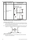
Control circuit terminals (U/T1, V/T2, W/T3)
When the AC drive output terminals U/T1, V/T2, and W/T3 are connected to the motor
terminals U/T1, V/T2, and W/T3, respectively, the motor will rotate counterclockwise (as
viewed on the shaft end of the motor) when a forward operation command is received.
To permanently reverse the direction of motor rotation, switch over any of the two motor
leads.
Forward
running