


Chapter 5 Parameters|VFD-S Series
5-72 Revision August 2006, SE08, SW V2.61
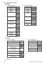
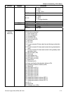
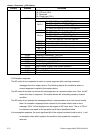
Content Address Functions
35: Reserved
36: PID error (Pld)
37: Reserved
38: Phase loss (PHL)
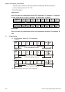
Status of AC Drive
00: RUN LED light off, STOP LED light up
01: RUN LED blink, STOP LED light up
10: RUN LED light up, STOP LED blink
Bit 0-1
11: RUN LED light up, STOP LED light off
Bit 2 01: Jog active
00: REV LED light off, FWD LED light up
01: REV LED blink, FWD LED light up
10: REV LED light up, FWD LED blink
Bit 3-4
11: REV LED light up, FRD LED light off
Bit 5-7 Not used
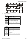
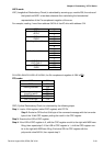
2101H
Bit 8 1: Main freq. Controlled by communication
Bit 9 1: Main freq. Controlled by external terminal
Bit 10
1: Operation command controlled by communication
Bit 11 1: Parameters have been locked
Bit 12-15 Not Used
2102H Frequency command F (XXX.XX)
2103H Output Frequency H (XXX.XX)
2104H Output Current A (XXX.XX)
2105H DC-BUS Voltage U (XXX.XX)
2106H Output Voltage E (XXX.XX)
2107H Step number of Multi-Step Speed Operation
2108H Step number of PLC operation
2109H Time of PLC Operation
210AH Counter Value
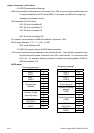
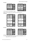
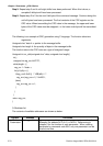
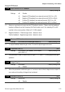
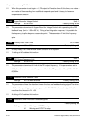
3.6 Exception response:
The AC motor drive is expected to return a normal response after receiving command
messages from the master device. The following depicts the conditions when no
normal response is replied to the master device.
The AC motor drive does not receive the messages due to a communication error; thus, the AC
motor drive has no response. The master device will eventually process a timeout
condition.
The AC motor drive receives the messages without a communication error, but cannot handle
them. An exception response will be returned to the master device and an error
message “CExx” will be displayed on the keypad of AC motor drive. The xx of “CExx”
is a decimal code equal to the exception code that is described below.
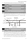
In the exception response, the most significant bit of the original command code is set to 1, and
an exception code which explains the condition that caused the exception is
returned.