


Chapter 2 Installation and Wiring|VFD-S Series
Revision August 2006, SE08, SW V2.61 2-27
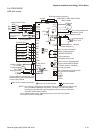
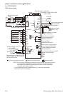
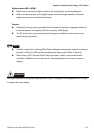
Digital outputs (MO1, MCM)
Make sure to connect the digital outputs to the right polarity, see wiring diagrams.
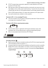
When connecting a relay to the digital outputs, connect a surge absorber or fly-back
diode across the coil and check the polarity.
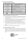
General
Keep control wiring as far as possible from the power wiring and in separate conduits to
avoid interference. If necessary let them cross only at 90º angle.
The AC motor drive control wiring should be properly installed and not touch any live
power wiring or terminals.
NOTE
If a filter is required for reducing EMI (Electro Magnetic Interference), install it as close as
possible to AC drive. EMI can also be reduced by lowering the Carrier Frequency.
When using a GFCI (Ground Fault Circuit Interrupter), select a current sensor with
sensitivity of 200mA, and not less than 0.1-second detection time to avoid nuisance
tripping.
DANGER!
Damaged insulation of wiring may cause personal injury or damage to circuits/equipment if it comes
in contact with high voltage.