


Chapter 2 Installation and Wiring|VFD-S Series
Revision August 2006, SE08, SW V2.61 2-23
DO NOT connect phase-compensation capacitors or surge absorbers at the output
terminals of AC motor drives.
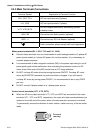
With long motor cables, high capacitive switching current peaks can cause over-current,
high leakage current or lower current readout accuracy. To prevent this, the motor cable
should be less than 20m for 3.7kW models and below. And the cable should be less than
50m for 5.5kW models and above. For longer motor cables use an AC output reactor.
Use a well-insulated motor, suitable for inverter operation.
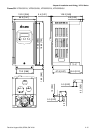
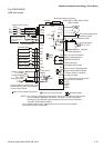
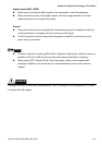
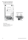
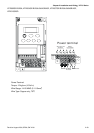
Terminals [+2/B1, +1] for connecting DC reactor
This is the connector for the DC reactor to improve the power factor. Please remove the
short jumper when connecting DC reactor.
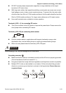
Terminals [+2/B1, B2] for connecting brake resistor
B2
BR
+2/B1
Connect a brake resistor in applications with frequent deceleration ramps, short
deceleration time, too low braking torque or requiring increased braking torque.
When not used, please leave the terminals [+2/B1, B2] open.
WARNING!
Short-circuiting [+2/B1, B2] can damage the AC motor drive.
Grounding terminals (
)
Make sure that the leads are connected correctly and the AC drive is properly grounded.
(Ground resistance should not exceed 0.1
Ω
.)
Use ground leads that comply with local regulations and keep them as short as possible.
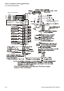
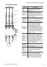
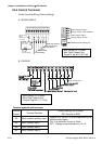
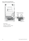
Multiple VFD-S units can be installed in one location. All the units should be grounded
directly to a common ground terminal, as shown in the figure below. Ensure there are
no ground loops.
goodexcellent
not allowed