


Chapter 5 Parameters|VFD-S Series
Revision August 2006, SE08, SW V2.61 5-31
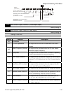
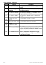
Group 3: Output Function Parameters
3-00
Analog Output Signal (AFM)
Factory Setting: d0
Settings d0 Analog Frequency Meter (0 to Maximum Output Frequency)
d1 Analog Current Meter (0 to 250% of rated AC motor drive current)
This parameter sets the function of the AFM output 0~+10VDC (ACM is common).
The voltage output type for this analog signal is PWM. It needs to read value by the movable
coil meter and is not suitable for A/D signal conversion.
3-01 Analog Output Gain Unit: 1
Settings d1 to d200% Factory Setting: d100
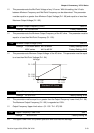
The parameter sets the voltage range of the analog output signal at terminals AFM, that
corresponds with either the output frequency or the output current of the VFD.
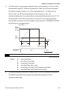
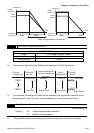
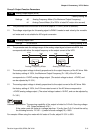
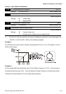
+-
AFM
GND
Analog Frequency Meter
+-
AFM
GND
Analog Current Meter
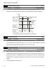
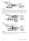
The analog output voltage is directly proportional to the output frequency of the AC drive. With
the factory setting of 100%, the Maximum Output Frequency (Pr.1-00) of the AC drive
corresponds to +10VDC analog voltage output. (The actual voltage is about +10VDC, and
can be adjusted by Pr.3-01).
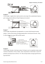
The analog output voltage is directly proportional to the output current of the AC drive. With
the factory setting of 100%, the 2.5 times rated current of the AC drive corresponds to
+10VDC analog voltage output. (The actual voltage is about +10VDC, and can be adjusted by
Pr. 3-01)
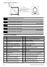
NOTE
Voltmeter specification: The sourcing capability of the output is limited to 0.21mA. Sourcing voltage:
10V. Output resistance: 47kΩ.
If the meter reads full scale at a voltage less than 10 volts, then Pr.3-01 should be set by
the following formula: Pr.3-01 = ((meter full scale voltage)/10) ×100%
For example: When using the meter with full scale of 5 volts, adjust Pr.3-01 to 50%.