


Chapter 5 Parameters|VFD-S Series
Revision August 2006, SE08, SW V2.61 5-5
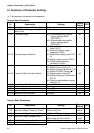
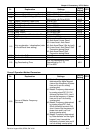
Pr. Explanation Settings
Factory
Setting
NOTE
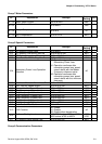
3-00 Analog Output Signal
d0: analog frequency meter
d1: analog current meter
d0
3-01 Analog Output Gain d1 to d200% d100
3-02 Desired Frequency Attained d1.0 to d400 Hz d1.0
3-03 Terminal Count Value d0 to d999 d0
3-04 Preliminary Count Value d0 to d999 d0
3-05
Multi-Function Output Terminal 1
(Photocoupler Output)
d0: No Function d1
3-06
Multi-Function Output Terminal 2
(Relay Output)
d1: AC Drive Operational
d2: Master Frequency Attained
d3: Zero Speed
d4: Over Torque Detection
d5: Base-Block (B.B.) Indication
d6: Low-Voltage Indication
d7: Operation Mode Indication
d8: Fault Indication
d9: Desired Frequency Attained
d10: PLC Program Running
d11: PLC Program Step Completed
d12: PLC Program Completed
d13: PLC Program Operation
Paused
d14: Terminal Count Value Attained
d15: Preliminary Count Value
Attained
d16: AC Motor Drive Ready
d17: FWD command Indication
d18: REV command Indication
d8
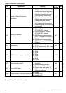
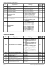
Group 4 Input Function Parameters
Pr. Explanation Settings
Factory
Setting
NOTE
4-00 Potentiometer Bias Frequency d 0.0 to d 100.0% d0.0
4-01
Potentiometer Bias
Polarity
d0: Positive Bias
d1: Negative Bias
d0
4-02
Potentiometer
Frequency Gain
d1 to d200 % d100
4-03
Potentiometer Reverse
Motion Enable
d0: Forward Motion Only
d1: Reverse Motion enabled
d0
4-04
Multi-Function Input Terminal 1 (M0,
M1)
d0: No Function
d1: FWD/STOP, REV/STOP
d2: FWD/REV, RUN/STOP
d3: 3-wire Operation Control Mode
d4: E.F. External Fault Input (N.O.)
d5: E.F. External Fault Input (N.C.)
d6: Reset
d7: Multi-Step Speed Command 1
d8: Multi-Step Speed Command 2
d9: Multi-Step Speed Command 3
d1