


Chapter 5 Parameters|VFD-S Series
Revision August 2006, SE08, SW V2.61 5-35
Group 4: Input Function Parameters
4-00 Potentiometer Bias Frequency Unit: 0. 1
Settings d0.0 to d100.0% Factory Setting: d0.0
4-01 Potentiometer Bias Polarity
Factory Setting: d0
Settings d0 Positive Bias
d1 Negative Bias
4-02 Potentiometer Frequency Gain Unit: 1
Settings d1 to d200% Factory Setting: d100
4-03 Potentiometer Reverse Motion Enable
Factory Setting: d0
Settings d0 Forward motion only
d1 Reverse motion enable (must be negative bias)
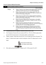
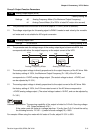
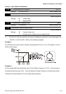
Pr.4-00 to Pr.4-03 are used when the source of frequency command is the analog signal (0 to
+10V DC or 4 to 20 mA DC). Refer to the following examples.
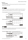
Example 1:
The following is the most common method. Set parameter 2-00 to d1 (0 to +10V signal) or d2 (4 to
20mA current signal).
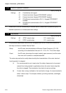
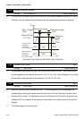
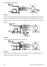
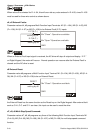
Example 2:
In this example with the potentiometer set to 0V the Output Frequency is 10 Hz. The mid-point of
the potentiometer becomes 40 Hz. Once the Maximum Output Frequency is reached any further
increase of the potentiometer will not increase output frequency.