


Chapter 2 Installation and Wiring|VFD-S Series
Revision August 2006, SE08, SW V2.61 2-17
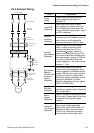
2.4.1 Basic Wiring
Make sure that power is only applied to the R/L1, S/L2, T/L3 terminals. Failure to comply
may result in damage to the equipment. The voltage and current should lie within the
range as indicated on the nameplate.
Check the following items after completing the wiring:
1. Are all connections correct?
2. No loose wires?
3. No short-circuits between terminals or to ground?
A charge may still remain in the DC bus capacitors with hazardous voltages even if the
power has been turned off. To prevent personal injury, please ensure that the power is
turned off and wait ten minutes for the capacitors to discharge to safe voltage levels
before opening the AC motor drive.
DANGER!
1. All the units must be grounded directly to a common ground terminal to prevent electric shock,
fire and interference.
2. Only qualified personnel familiar with AC motor drives are allowed to perform installation, wiring
and commissioning.
3. Make sure that the power is off before doing any wiring to prevent electric shocks.
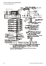
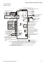
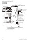
Basic Wiring Diagrams
Users must connect wires according to the circuit diagrams on the following pages. Do not plug a
modem or telephone line to the RS-485 communication port or permanent damage may result.
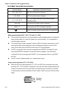
Terminals 1 & 2 are the power supply for the optional copy keypad only and should not be used for
RS-485 communication.