


Chapter 5 Parameters|VFD-S Series
5-6 Revision August 2006, SE08, SW V2.61
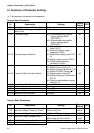
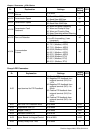
Pr. Explanation Settings
Factory
Setting
NOTE
4-05
Multi-Function Input Terminal 2 (M2) d10: Jog Operation
d11: Accel/decel Inhibit
d6
4-06
Multi-Function Input Terminal 3 (M3) d12: First or Second
Acceleration/deceleration Time
Selection
d13: External base block (N.O.)
d14: External base block (N.C.)
d7
4-07
Multi-Function Input Terminal 4 (M4) d15: Up: Increment master
frequency
d16: Down: Decrement master
frequency
d17: Run PLC Program
d8
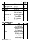
4-08 Multi-Function Input Terminal 5(M5)
d18: Pause PLC Program
d19: Counter Trigger Signal
d20: Counter Reset
d21: Select ACI / Deselect AVI
d22: PID Function Disabled
d23: JOG FWD
d24: JOG REV
d25: The source of master
frequency is AVI.
d26: The source of master
frequency is ACI.
d27: Press UP/DOWN key to switch
forward/reverse (N.O.) motion
d28: Press UP/DOWN key to switch
forward/reverse (N.C.) motion
d29: M0: 0: RUN 1: STOP, M1: no
function, Direction is controlled
by keypad
d9
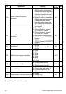
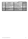
4-09 Line Start Lockout
d0: Disable
d1: Enable
d0
4-10 Up/Down Mode
d0: Based on accel/decel time
d1: Up frequency according to
constant speed, down frequency
according to deceleration time
d2: Up frequency according to
acceleration time, down
frequenc according to constant
speed
d3: Constant speed
d3
4-11
Accel/Decel Rate of Change of
UP/DOWN Operation with Constant
Speed
0~1000, unit: 5 Hz/sec d1
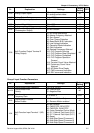
Group 5 Multi-Step Speed and PLC Parameters
Pr. Explanation Settings
Factory
Setting
NOTE
5-00 1st Step Speed Freq. d0.0 to d400 Hz d0.0
5-01 2nd Step Speed Freq. d0.0 to d400 Hz d0.0