


Chapter 2 Installation and Wiring|VFD-S Series
2-26 Revision August 2006, SE08, SW V2.61
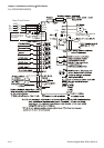
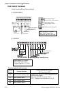
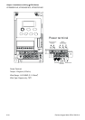
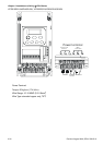
Terminal
Symbol
Terminal Function
Factory Settings (NPN mode)
ON: Connect to GND
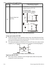
AVI
Analog voltage Input
(AVI/ACI)
0~+10V/4-20mA corresponds to 0-max.
operation frequency (Pr.01-00)
PID feedback signal
AVI input impedance: 100kohm
ACI input impedance: 250kohm
GND
A
VI
+10V
Internal Circuit
AVI circuit
AVI
J1
ACI
GND
ACI
Internal Circuit
ACI circuit
AVI
J1
ACI
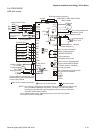
Control signal wiring size: 18 AWG (0.75 mm
2
) with shielded wire.
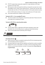
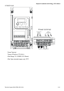
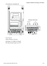
Analog input terminals (AVI, GND)
Analog input signals are easily affected by external noise. Use shielded wiring and keep
it as short as possible (<20m) with proper grounding. If the noise is inductive, connecting
the shield to terminal GND can bring improvement.
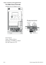
If the analog input signals are affected by noise from the AC motor drive, please connect
a capacitor (0.1
μ
F and above) and ferrite core as indicated in the following diagrams:
C
AVI
GND
ferrite core
wind each wires 3 times or more around the core
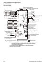
Digital inputs (M0~M5, GND)
When using contacts or switches to control the digital inputs, please use high quality
components to avoid contact bounce.