


Chapter 5 Parameters|VFD-S Series
Revision August 2006, SE08, SW V2.61 5-37
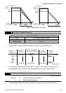
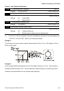
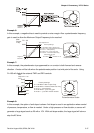
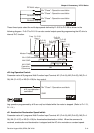
Example 6:
In this example, a negative bias is used to provide a noise margin. Also a potentiometer frequency
gain is used to allow the Maximum Output Frequency to be reached.
Hz
0V
10V
27
0
54
Potentiometer Scale
Max.
Output
Freq.
60Hz
Pr.1-00
0Hz
0V
10V
Factory Settings
Pr.1-00=60Hz--Max. output Freq.
Pr.4-00=10%--Potentiometer bias freq.
Pr.4-01=1 -- Bias polarity
Pr.4-02=111% -- Pot. freq. gain
Pr.4-03=0 -- Forward motion only
Negative
bias 6H
z
1V
It's 0Hz
within
this
range.
Gain adjustment
Calculation of gain
Pr.4-02=(
10V
9V
)X100%=111%
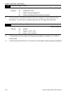
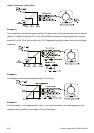
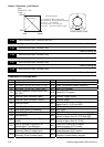
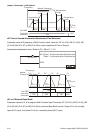
Example 7:
In this example, the potentiometer is programmed to run a motor is both forward and reverse
direction. A motor will be idle when the potentiometer position is at mid-point of its scale. Using
Pr.4-03 will disable the external FWD and REV controls.
Hz
0V
10V
0
60
Potentiometer Scale
Max.
Output
Freq.
Pr.1-00
Factory Settings
Pr.1-00=60Hz--Max. output Freq.
Pr.4-00=30Hz--Potentiometer bias freq.
Pr.4-01=1 -- bias polarity
Pr.4-02=200% -- pot. freq. gain
Pr.4-03=1 -- pot. REV motion enable
60Hz
30Hz
0Hz
0V
5V
10V
30Hz
60Hz
REV
FWD
REV.
FWD.
60
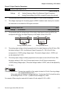
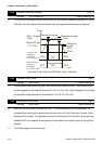
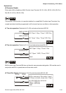
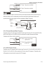
Example 8:
In this example, the option of anti-slope is shown. Anti-slope is used in an application where control
of pressure, temperature, or flow is needed. Under a high pressure or flow situation, a sensor will
generate a large signal such as 20 mA or 10V. With anti-slope enable, the large signal will slow or
stop the AC drive.