


Chapter 5 Parameters|VFD-S Series
Revision August 2006, SE08, SW V2.61 5-75
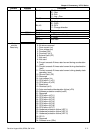
Group A: PID Control
A-00
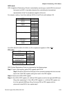
Input Terminal for PID Feedback
Factory Setting: d0
Settings d0 Disable
d1 Negative PID feedback from external terminal (AVI) 0 to +10V
d2 Negative PID feedback from external terminal (ACI) 4 to 20mA
d3 Positive PID feedback from external terminal (AVI) 0 to +10V
d4 Positive PID feedback from external terminal (ACI) 4 to 20mA
Select an input terminal to serve as the PID feedback location. Please verify the feedback
location is different from the Frequency Set Point location and J1 for selecting ACI or AVI
must be in the correct position. (Refer to Pr. 2-00 for detail)
Negative feedback = Positive target value – detection value.
Positive feedback = Negative target value + detection value.
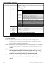
A-01 Gain over PID Detection value
Settings d0 to d999 (d100 means gain value is 1) Factory Setting: d100
To adjust feedback detective gain value. It is used to adjust target value error.
A-02 Proportional Gain (P) Unit: 1
Settings d0 to d999% (d0: disable) (d100 means
gain value is 1)
Factory Setting: d100
This parameter is used to determinate error gain. If I = 0 and D = 0, doing proportional gain
operation.
A-03 Integral Time (I) Unit: 1
Settings d0 to d999 Factory Setting: d100
d0 Disable
When this parameter is defined to gain is 1 and error value is fixed, integral value is equal to
error value as the setting of integral time is attained.
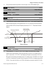
A-04 Derivative Control (D) Unit: 1
Settings d0 to d100 Factory Setting: d0
d0 Disable