


Chapter 5 Parameters|VFD-S Series
Revision August 2006, SE08, SW V2.61 5-27
Group 2: Operation Method Parameters
2-00 Source of Master Frequency Command
Factory Setting: d0
Settings d0 Master Frequency input determined by digital keypad. (record the
frequency of power loss and it can do analog overlap plus)
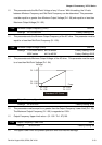
d1 Master Frequency determined by analog signal DC 0V-10V
(external terminal AVI). (won’t record the frequency of power loss
and it can’t do analog overlap plus)
d2 Master Frequency determined by analog signal DC 4mA-20mA
(external terminal AVI). (won’t record the frequency of power loss
and it can’t do analog overlap plus)
d3 Master Frequency determined by Potentiometer on the digital
keypad. (won’t record the frequency of power loss and it can do
analog overlap plus)
d4 Master Frequency operated by RS-485 serial communication
interface and record frequency of power loss. (record the frequency
of power loss and it can do analog overlap plus)
d5 Master Frequency operated by RS-485 serial communication
interface and won’t record frequency before power loss. (won’t
record the frequency of power loss and it can do analog overlap
plus)
This parameter sets the Frequency Command Source of the AC drive.
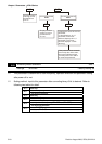
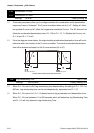
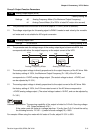
If the Frequency Command Source is external (DC 0 to +10V or 4 to 20mA), please make
sure the (AVI) terminal jumper is in the proper position as shown below.
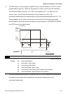
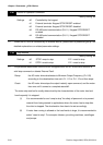
Position of jumper: Please open the top cover. It is at the lower-left corner of the panel. The
jumper J1 determines the type of external analog input, either DC voltage signal or current
signal.
J1
V
oltage signal input(0-10V)
Current signal input(4-20mA)
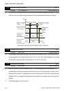
When setting analog overlap plus, it needs to set Pr. 2-06 to select AVI or ACI.