


Chapter 2 Installation and Wiring|VFD-S Series
Revision August 2006, SE08, SW V2.61 2-21
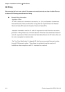
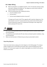
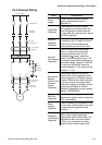
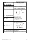
2.4.2 External Wiring
Motor
Output AC
Line Reactor
Power Supply
Magnetic
contactor
Input AC
Line Reactor
EMI Filter
R/L1 S/L2
T/L3
U/T1 V/T2
W/T3
+2/B1
B2
Braking
Resistor
Zero-phase
Reactor
DC
Choke
+1
Zero-phase
Reactor
FUSE/NFB
Items Explanations
Power
supply
Please follow the specific power
supply requirements shown in
Appendix A.
Fuse/NFB
(Optional)
There may be an inrush current
during power up. Please check the
chart of Appendix B and select the
correct fuse with rated current. Use of
an NFB is optional.
Magnetic
contactor
(Optional)
Please do not use a Magnetic
contactor as the I/O switch of the AC
motor drive, as it will reduce the
operating life cycle of the AC drive.
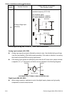
Input AC
Line Reactor
(Optional)
Used to improve the input power
factor, to reduce harmonics and
provide protection from AC line
disturbances.
(surges, switching
spikes, short interruptions, etc.). AC
line reactor should be installed when
the power supply capacity is 500kVA
or more and exceeds 6 times the
inverter capacity, or the mains wiring
distance
≤
10m.
Zero-phase
Reactor
(Ferrite Core
Common
Choke)
(Optional)
Zero phase reactors are used to
reduce radio noise especially when
audio equipment is installed near the
inverter. Effective for noise reduction
on both the input and output sides.
Attenuation quality is good for a wide
range from AM band to 10MHz.
Appendix B specifies the zero phase
reactor. (RF220X00A)
EMI filter
(Optional)
To reduce electromagnetic
interference, please refer to Appendix
B for more details.
Brake
resistor
(Optional)
Used to reduce the deceleration time
of the motor. Please refer to the chart
in Appendix B for specific brake
resistors.
Output AC
Line Reactor
(Optional)
Motor surge voltage amplitude
depends on motor cable length. For
applications with long motor cable
(>20m), it is necessary to install a
reactor at the inverter out
p
ut side.