


Chapter 5 Parameters|VFD-S Series
Revision August 2006, SE08, SW V2.61 5-33
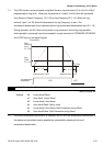
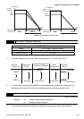
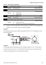
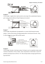
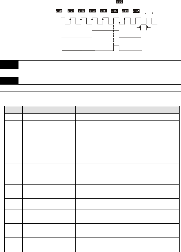
Preliminary Counter Value Attained Output
(Pr. 3-04=d3)
(Pr. 3-05 to Pr. 3-06=d15)
Terminal Count Value Attained Output
(Pr.3-03=d5)
(Pr.3-05 to Pr.3-06=d14)
Display
(Pr.0-04=d1)
TRG
Counter Trigger Signal
Multi-function Input Terminal
The width of tri
gg
er si
g
nal
should not be less than
2ms(<250 Hz)
2ms
2ms
3-05
Multi-function Output Terminal 1 (Photocoupler output)
Factory Setting: d1
3-06
Multi-function Output Terminal 2 (relay output)
Factory Setting: d8
Settings d0 to d18
Setting Function Description
d0 No Function
d1 AC Drive Operational the output terminal will be activated when the drive is
running.
d2
Master Frequency Attained the output will be activated when the AC drive attains
Maximum Output Frequency.
d3 Zero Speed the output will be activated when Command Frequency
is lower than the Minimum Output Frequency.
d4 Over Torque Detection the output will be activated as long as the over-torque is
detected. Pr.6-04 determines the Over-Torque detection
level.
d5 Base-Block (B.B.) Indication the output will be activated when the output of the AC
drive is shut off by external Baseblock.
d6 Low-Voltage Indication the output will be activated when low voltage is detected.
d7 Operation Mode Indication the output will be activated when the operation of the AC
drive is controlled by External Control Terminals.
d8 Fault Indication the output will be activated when faults occur (oc, ov,
oH, oL, oL1, EF, cF3, HPF, ocA, ocd, ocn, GF).
d9 Desired Frequency Attained the output will be activated when the desired frequency
(Pr.3-02)is attained.