


INSTALLATION
A-6 A-6
OUTBACK® 185
Return to Section TOC Return to Section TOC Return to Section TOC Return to Section TOC
Return to Master TOC Return to Master TOC Return to Master TOC Return to Master TOC
MACHINE GROUNDING
Because this portable engine driven welder or genera-
tor creates its own power, it is not necessary to connect
its frame to an earth ground, unless the machine is
connected to premises wiring (your home, shop, etc.).
To prevent dangerous electric shock, other equipment
to which this engine driven welder supplies power,
must:
a) be grounded to the frame of the welder using a
grounded type plug
or
b) be double insulated
When this welder is mounted on a truck or trailer, the
machine grounding stud must be securely con-
nected to the metal frame of the vehicle.
In general if the machine is to be grounded, it should
be connected with a #8 or larger copper wire to a solid
earth ground such as a metal water pipe going into the
ground for at least ten feet and having no insulated
joints, or to the metal framework of a building which
has been effectively grounded. The U.S. National
Electrical Code lists a number of alternate means of
grounding electrical equipment. A machine grounding
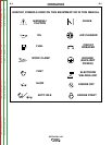
stud marked with the symbol is provided on the
front of the welder.
DO NOT GROUND MACHINE TO A PIPE WHICH CAR-
RIES EXPLOSIVE OR COMBUSTIBLE MATERIAL.
------------------------------------------------------------------------
WARNING
CAUTION
• Loose connections will cause the output studs to
overheat and the studs may eventually melt.
• Do not cross welding cables at output stud connec-
tion. Keep isolated and separate from one another.
------------------------------------------------------------------------
Lincoln Electric offers a welding accessory kit with #6
welding cables. See the ACCESSORIES section of
this manual for more information.
For more information on welding , see WELDING
OPERATION in the OPERATION section of this man-
ual.
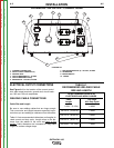
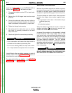
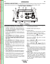
Cable Installation
Install the welding cables to your OUTBACK® 185 as
follows. See Figure A.1 for the location of parts.
1. The gasoline engine must be OFF to install weld-
ing cables.
2. Remove the 1/2-13 flanged nuts from the output
terminals.
3. Connect the electrode holder and work cables to
the weld output terminals. Normally, the electrode
cable is connected to the positive (+) output stud.
4. Tighten the flanged nuts securely.
5. Be certain that the metal piece you are welding
(the “work”) is securely connected to the work
clamp and cable.
6. Check and tighten the connections periodically.