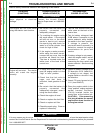
OUTPUT PROBLEMS
Observe Safety Guidelines detailed in the beginning of this manual.
PROBLEMS
(SYMPTOMS)
POSSIBLE AREAS OF
MISADJUSTMENT(S)
RECOMMENDED
COURSE OF ACTION
If for any reason you do not understand the test procedures or are unable to perform the tests/repairs safely,
contact the Lincoln Electric Service Department for technical troubleshooting assistance before you proceed.
Call 1-888-935-3877.
CAUTION
Major physical or electrical
damage.
Contact the Lincoln Electric
Service Department at 1-888-935-
3877.
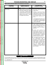
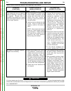
The engine will not crank while
using the electric start function.
1. Be certain that the battery is
properly connected and
adequately charged.
2. Try cranking the engine using
the recoil starter. If the engine
will still not turn, or the recoil
starter is hard to pull, remove
the spark plug and check for
water or oil in the cylinder. Also
check for high oil level.
3. If the engine cranks normally
while using the recoil starter,
remove the top cover from the
machine ad check the fuse.
The fuse is located under the
white cover of the back of the
control box.
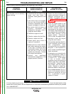
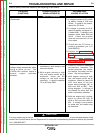
1. Test the fuse located under the
white cover at the back of the
control box.
2. Test for battery voltage at lead
210B where it connects to the
starter solenoid, while holding
the switch in the “start” position.
If voltage is present, the
starter/solenoid assembly is
defective; contact the engine
manufacturer for parts and
service.
3. If battery voltage is not present,
check the engine switch, and all
connectors and wires
connecting the fuse, switch and
starter solenoid. See the wiring
diagram.
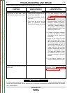
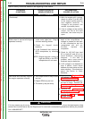
Engine will not start. The starter
motor will crank the engine
normally.
1. If using the recoil starter, be
sure the engine switch is in the
“high” or “auto” position.
2. Check that the fuel valve is
open, and that there is
sufficient, fresh gasoline in the
tank.
3. Be certain that the battery is
properly connected and
adequately charged, even if
using the recoil starter.
4. Check the engine oil level.
5. Check or replace the fuel filter.
6. Check or replace air filter.
7. Check the spark plug. Clean or
replace if necessary.
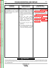
1. Check for battery voltage at the
PC board pin J3-10. (lead #211)
If voltage is not resent, the
engine switch or wire #211 may
be defective.
2. Check PC board ground at pin
J1-2. (lead GND-G)
3. Place the engine switch in the
“stop” position, unplug engine to
welder harness connector
(P4/J4) located inside the
control box at the bottom left.
CAUTION: Disconnecting
this plug disables the normal
engine shut down function of
the engine switch.
TROUBLESHOOTING AND REPAIR
F-4 F-4
OUTBACK® 185
Return to Section TOC Return to Section TOC Return to Section TOC Return to Section TOC
Return to Master TOC Return to Master TOC Return to Master TOC Return to Master TOC


