


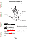


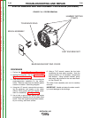
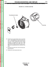


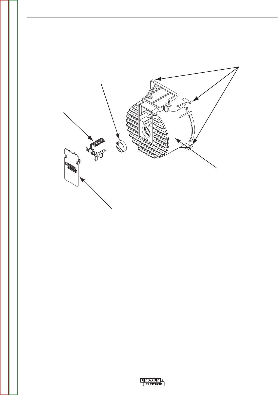
TOLERANCE RING
BRUSH ASSEMBLY
BEARING BRACKET END COVER
CAST END BRACKET
HAMMER TAPPING
POINTS
FIGURE F.18 – STATOR REMOVAL
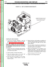
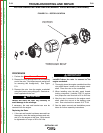
STATOR REMOVAL AND REPLACEMENT PROCEDURE (continued)
PROCEDURE
1. Perform the Control Box Removal Procedure.
2. Remove the brushes. See the Brush and Slip
Ring Service Procedure.
3. Label and disconnect any wiring connecting the
engine/generator assembly to the tubular
frame. Remove cable ties and flexible plastic
conduit as needed. See wiring diagram.
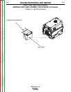
4. Using the 1/2” wrench, remove the nuts secur-
ing the generator and engine to the rubber
mounts. Note ground lead and washer place-
ment for reassembly. See Figure F.19.
5. Use a hoist or get a helper and lift the engine
and generator assembly out of the tubular steel
frame. Place the engine and generator assem-
bly on a strong, solid work surface.
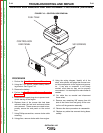
6. Using a 7/16” wrench, remove the four bolts
connecting the cast stator brackets. Note the
precise position of all hardware components
and washers. Using a plastic hammer, gently
and evenly tap outward on the end cast brack-
et. See Figure F.18.
The stator frame assembly can now be carefully
removed.
IMPORTANT: Handle and store the stator careful-
ly to avoid damage to the windings.
TROUBLESHOOTING AND REPAIR
F-48 F-48
OUTBACK® 185
Return to Section TOC Return to Section TOC Return to Section TOC Return to Section TOC
Return to Master TOC Return to Master TOC Return to Master TOC Return to Master TOC