


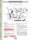

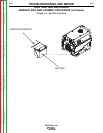
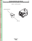

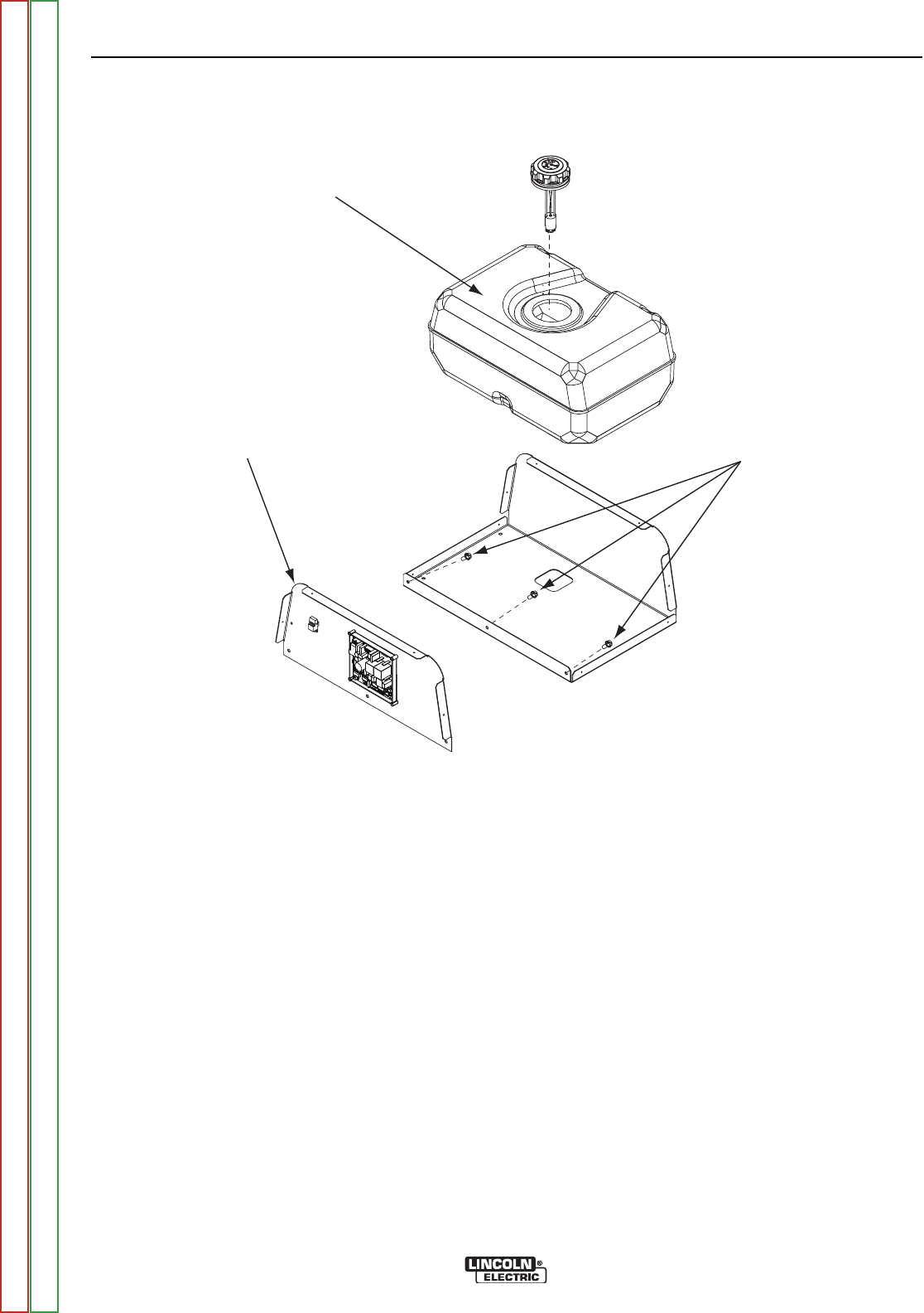
3/8’ SCREWS
CONTROL BOX
END PANEL
FUEL TANK
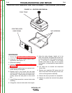
FIGURE F.16 – CONTROL BOX REMOVAL
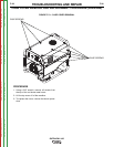
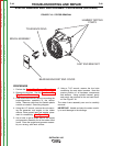
CONTROL BOX REMOVAL AND REPLACEMENT PROCEDURE (continued)
PROCEDURE
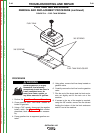
1. Perform the Case Cover Removal Procedure.
2. Using the 7/16” wrench, loosen battery mount-
ing bracket. See Figure F.16.
3. Remove the battery.
4. Perform the Fuel Tank and Enclosure Removl
Procedure.
5. Disconnect the spark plug wire to prevent acci-
dental starting of the engine.
6. Replace three of the screws that had been
removed when the fuel tank enclosure bottom
was removed. These screws are used to tem-
porarily secure the end panel on the control
box.
7. Using Phillips screwdriver, remove choke cable
mounting.
8. Using pliers, remove choke cable from engine.
9. Using the wiring diagram, identify all of the
wires, wire splices, and plugs that connect con-
trol box components to the engine and genera-
tor. If any wire or connector is not clearly
marked, mark them so they can be properly
reconnected. It is also helpful to make notes as
needed.
10. Cut cable ties as needed and disconnect
these wires.
11. Remove any remaining 3/8” screws from left
side of the control box and gently lift the con-
trol box off the generator assembly.
12. Reverse the above procedure to reassemble.
13. Replace any cable ties removed during disas-
sembly.
TROUBLESHOOTING AND REPAIR
F-44 F-44
OUTBACK® 185
Return to Section TOC Return to Section TOC Return to Section TOC Return to Section TOC
Return to Master TOC Return to Master TOC Return to Master TOC Return to Master TOC