


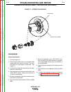
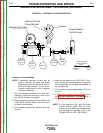
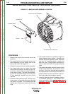
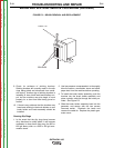

FAN BLADE
STROBE-TACH MARK
FIGURE F.1 – STROBE-TACH METHOD
ENGINE RPM ADJUSTMENT PROCEDURE (continued)
PROCEDURE
Strobe-Tach Method
1. Turn the engine off.
2. Place a highly visible mark on a component that
rotates while the engine is running. The rotor-
cooling fan is a good place for this mark. See
Figure F.1.
3. Connect the strobe-tach according to the man-
ufacturer’s instructions.
4. Start the engine and place the idle switch in the
“HIGH IDLE” position. Make sure that there is
no load on the machine.
5. Direct the strobe-tach light at the mark and syn-
chronize the strobe-tach.
6. The tach should read between 3700 and 3800
RPM.
7. Move the idle switch to the “AUTO IDLE” posi-
tion and wait for the idle solenoid to energize.
The engine RPM should drop and stabilize at
the low idle RPM.
8. Synchronize the strobe-tach to read the low idle
RPM.
9. The tach should read between 2250 and 2500
RPM.
10. If either of the readings is incorrect, proceed to
the Throttle Adjustment Procedure in this
section.
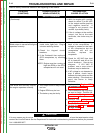
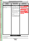
TROUBLESHOOTING AND REPAIR
F-14 F-14
OUTBACK® 185
Return to Section TOC Return to Section TOC Return to Section TOC Return to Section TOC
Return to Master TOC Return to Master TOC Return to Master TOC Return to Master TOC