


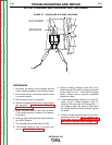


+
-
BATTERY
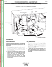
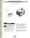
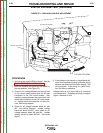
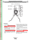
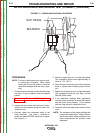
FIGURE F.8 – CHARGING SYSTEM
BATTERY CHARGING SYSTEM TEST (continued)
TROUBLESHOOTING AND REPAIR
F-26 F-26
OUTBACK® 185
Return to Section TOC Return to Section TOC Return to Section TOC Return to Section TOC
Return to Master TOC Return to Master TOC Return to Master TOC Return to Master TOC
PROCEDURE
DO NOT REMOVE BATTERY
CABLE WHILE MACHINE IS RUN-
NING, OR ATTEMPT TO OPERATE
THE ENGINE WITHOUT A BAT-
TERY CONNECTED. Serious dam-
age to the PC board may result.
1. Be sure the battery is fully charged, in good
condition and is securely connected.
2. Start the engine and test the voltage at the bat-
tery terminals. The meter should read between
13.5 and 14.5 volts DC.
3. If the voltage is low, shut off the engine.
4. Disconnect lead #208 from the engine alterna-
tor and place a fused jumper lead between the
alternator and the positive battery terminal.
See Figure F.8. See wiring diagram.
5. Start the engine and check voltage at the bat-
tery. If the DC voltage is now 13.5 to 14.5,
check leads 208, 208A, and lead 209. If these
leads and connections are good, replace the
board.
6. If the voltage is still low, or if the inline fuse
blows, the engine charging system is most like-
ly faulty. Contact a qualified engine repair tech-
nician.
WARNING