


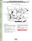
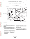


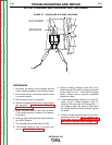
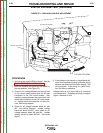
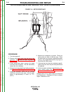

+
-
BRUSHES
SLIP RINGS
FIGURE F.7 – BRUSH AND SLIP RING LOCATIONS
ROTOR FLASHING AND VOLTAGE TEST (continued)
PROCEDURE
1. Be certain the battery is fully charged and the
battery charging system is functioning normally.
2. Ensure that there is no load on either the weld
or auxiliary outputs.
3. Set the output control to maximum.
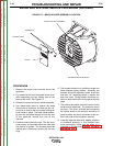
4. Remove the plastic brush cover from the end of
the generator. See Brush and Slip Ring
Service Procedure.
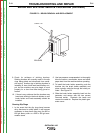
5. Attach voltmeter leads to the brush terminals.
(The positive terminal is closest to the genera-
tor winding)
6. Start the engine and place the engine switch in
the “HIGH” position.
7. The voltmeter should read about 50 VDC.
8. If the voltage reading is zero or near zero, per-
form the Rotor Resistance Test.
9. Check for battery voltage at lead 224 (J1-9).
Check that the PC board is properly grounded
at lead GND-G (J1-2). If the board is getting
battery voltage and is properly grounded,
replace the board.
10. If the voltage reading is about 3 to 5 volts DC,
check for AC voltage between Lead #7
(Terminal B2) and Lead #9 (Terminal B1). If
the voltage is about the same or higher than
the voltage reading of the brush leads, replace
the board.
11. If the AC voltage between leads #7 and #9 is
significantly lower than the DC voltage on the
brush leads, perform the Stator Short Circuit
and Ground Test and Stator Voltage Test.
TROUBLESHOOTING AND REPAIR
F-24 F-24
OUTBACK® 185
Return to Section TOC Return to Section TOC Return to Section TOC Return to Section TOC
Return to Master TOC Return to Master TOC Return to Master TOC Return to Master TOC