


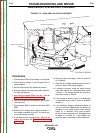

+
-
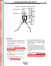
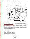
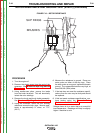
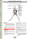
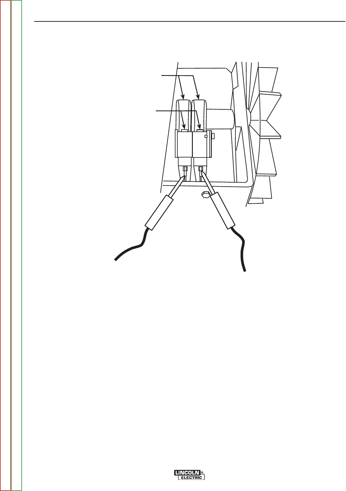
BRUSHES
SLIP RINGS
FIGURE F.10 – ROTOR RESISTANCE
ROTOR RESISTANCE AND GROUND TEST (STATIC) (continued)
PROCEDURE
1. Turn the engine off.
2. Remove the plastic cover from the end of the
generator. See Brush and Slip Ring Service
Procedure.
3. Using needle-nose pliers, remove the leads
from the brush terminals. This will electrically
isolate the rotor windings.
4. Remove the brush and brush holder assembly.
See Brush and Slip Ring Service Procedure.
5. Using the ohmmeter, check the rotor winding
resistance across the slip rings. Normal resis-
tance is approximately 9* ohms, at 77°F.
(25°C.)
6. Measure the resistance to ground. Place one
meter probe on either of the slip rings. Place
the other probe on any good, unpainted chassis
ground. The resistance should be very high, at
least 500,000 (500k) ohms.
7. If the test does not meet the resistance specifi-
cations, then the rotor may be faulty and should
be replaced.
8. If this test meets resistance specifications, con-
tinue testing using the Dynamic Rotor
Resistance and Ground Test.
*Voltage shown is for a stator that is at normal full
load temperature. Readings will likely be slightly
higher if machine is cold.
TROUBLESHOOTING AND REPAIR
F-30 F-30
OUTBACK® 185
Return to Section TOC Return to Section TOC Return to Section TOC Return to Section TOC
Return to Master TOC Return to Master TOC Return to Master TOC Return to Master TOC