


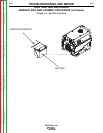


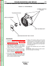

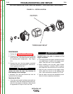


RUBBER ENGINE MOUNT
“OTHER ENGINE MOUNTS NOT
VISIBLE FROM THIS ANGLE
”
FIGURE F.19 – NUTS & RUBBER ENGINE MOUNTS
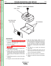
STATOR REMOVAL AND REPLACEMENT PROCEDURE (continued)
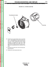
Installing the stator assembly:
1. If the rotor has been removed, it must be
replaced before installation of the stator assem-
bly. See the Rotor Removal Procedure.
Important! Always use a new tolerance ring
when reassembling the brush-end end bracket.
It is also highly recommended that the bearing
be replaced.
2. Examine the cast end brackets and the stator
assembly. Be sure the locating points are free
of varnish and any debris.
3. Place the stator in the cast end bracket.
4. Clean the bearing recess in the brush end
bracket and install a new tolerance ring.
5. Place the brush end bracket over the stator.
Use a plastic or rubber hammer to tap the
bracket in place.
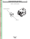
6. Adjust the stator and brackets as needed and
install the stator through bolts, placing the hard-
ware components the same as they were
before removal.
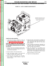
7. Place the engine and generator assembly into
the tubular frame of the machine and loosely
install the rubber mount fasteners.
8. Make final adjustments to the position of the
brackets and stator. The stator lead bundle
should exit the end bracket at the center of the
hole provided. Evenly tighten the stator through
bolts to a torque of 4.5 to 5.5 ft-lbs.
9. Tighten the mounting fasteners.
TROUBLESHOOTING AND REPAIR
F-49 F-49
OUTBACK® 185
Return to Section TOC Return to Section TOC Return to Section TOC Return to Section TOC
Return to Master TOC Return to Master TOC Return to Master TOC Return to Master TOC