


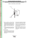


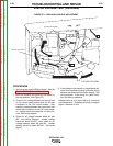
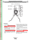

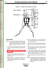
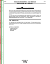

HIGH IDLE ADJUSTMENT
LOW IDLE ADJUSTMENT
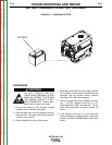
TOP VIEW OF ENGINE
FIGURE F.9 – HIGH AND LOW IDLE ADJUSTMENT
STATOR VOLTAGE TEST (continued)
PROCEDURE
1. Verify that the engine RPM is normal. See the
Engine RPM Adjustment Procedure.
2. Start the machine and place the idle switch in
the high position. See Figure F.9.
3. Check for AC voltage between the neutral stud
on the control panel bottom and the #3 lead
connection at the CB1 circuit breaker. Also
check the voltage between the neutral stud and
the #6 lead connection at the CB1 circuit break-
er. Voltage should read between 115 and 130*
volts. See wiring diagram.
4. Check for AC voltage between leads W1 and
W2. See Wiring Diagram. Voltage reading
should be about 64*VAC. Also check for AC
voltage between leads W3 and W4. Voltage
reading should be about 62*VAC. See wiring
digram.
5. If the voltage is not present or is significantly dif-
ferent from expected readings, check the wiring
between test points and the stator winding. See
wiring diagram. If the wiring is in good condi-
tion, the stator is defective.
*Voltage shown is for a stator that is at normal full
load temperature. Readings will likely be slightly
higher if machine is cold.
TROUBLESHOOTING AND REPAIR
F-28 F-28
OUTBACK® 185
Return to Section TOC Return to Section TOC Return to Section TOC Return to Section TOC
Return to Master TOC Return to Master TOC Return to Master TOC Return to Master TOC