


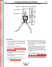

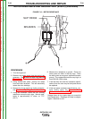
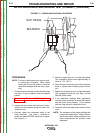


+
-
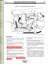
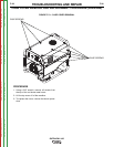
BRUSHES
SLIP RINGS
FIGURE F.11 – BRUSH AND SLIP RING LOCATIONS
ROTOR RESISTANCE AND GROUND TEST (DYNAMIC) (continued)
PROCEDURE
NOTE: This test is performed using a good quali-
ty analog type ohmmeter. Many digital
meters will not provide stable or accurate
resistance readings while the rotor is spin-
ning.
1. This test requires that the brushes and slip rings
are clean, in good condition, and are properly
seated.
2. Perform the Brush and Slip Ring Service
Procedure. Then reinstall the brush holder and
brush assembly.
3. Insulate the lead wires that had been discon-
nected from the brushes during the static rotor
resistance test.
4. Securely attach the ohmmeter leads to the
brush terminals. Use clips or terminals to
attach the leads BEFORE starting the engine.
See Figure F.11.
5. Start the engine and run it at high idle speed.
The resistance should read approximately 9*
ohms at 77°F. (25°C.)
6. Shut off engine, and move one of the ohmmeter
leads to a good clean chassis ground connec-
tion.
7. Restart the engine and run it at high idle speed.
The resistance should be very high, at least
500,000 (500k) ohms.
8. If the resistance readings differ significantly
from the values indicated, re-check the brushes
and the brush spring tension. If the brushes
and slip rings are good, replace the rotor.
9. Re-attach the brush leads and install the brush
cover.
*NOTE: The resistance of the copper windings will
change the temperature. Higher temper-
atures will produce higher resistance, and
lower temperatures will produce lower
resistance.
TROUBLESHOOTING AND REPAIR
F-32 F-32
OUTBACK® 185
Return to Section TOC Return to Section TOC Return to Section TOC Return to Section TOC
Return to Master TOC Return to Master TOC Return to Master TOC Return to Master TOC