


THEORY OF OPERATION
E-5 E-5
OUTBACK® 185
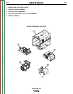
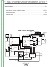
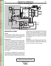
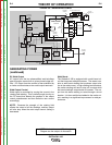
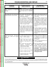
GENERATING POWER
Flashing
When the engine is running, power from the engine
charging system is stabilized, and then applied to the
rotor brushes through a series of PC board mounted
current limiting resistors and a “flashing” diode.
Building Output
The flashing current produces a weak magnetic field in
the rotor, which is coupled to the now running engine.
This rotating magnetic field begins to generate AC out-
put from all of the stator windings. Output from the
exciter winding is rectified by a diode bridge, filtered by
a capacitor, controlled by circuitry on the PC board,
and fed back into the rotating field winding, making the
magnetic field stronger. This stronger magnetic field
then produces higher voltage from the stator windings,
which feeds back to the rotor, making its magnetic field
even stronger.
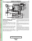
This process of strengthening the magnetic field
through feedback from the exciter winding continues to
increase the output of the main generator. If the output
control is set to maximum and the idle switch is in the
FIGURE E.5 - GENERATING POWER
“high” position, all of the windings should be putting out
maximum voltage almost immediately. The rotor field
voltage is now considerably higher than the flashing
voltage that was used to start the generating process.
The “flashing” diode on the control PC board blocks
that higher field voltage from intruding into the 12VDC
battery system.
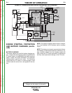
AC Output
The generator is now producing normal AC power from
all four of the windings. These windings consist of two
64 VAC weld windings, a 120/240 VAC auxiliary power
winding, and an 82 VAC excitation winding.
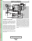
NOTE: Unshaded areas of Block Logic
Diagram are the subject of discussion
Return to Section TOC Return to Section TOC Return to Section TOC Return to Section TOC
Return to Master TOC Return to Master TOC Return to Master TOC Return to Master TOC
+
CB1
CB3
CB2
CB4
__
++
_
+
240 VAC
RECEPTACLE
ENGINE
OIL
LEVEL
MODULE
(KOHLER)
OIL LEVEL
INDICATOR
OIL LEVEL
SWITCH
IGNITION
STATOR
ROTOR
OFF
AUTO
HIGH
START
ALTERNATOR
IDLE
SOLENOID
SLIP
RINGS
AUXIIARY WINDINGS
WELD
WINDINGS
REACTOR
EXCITER
WINDING
CURRENT
SENSOR
120 VAC RECEPTACLES
BOOST
WINDING
OUTPUT
RECTIFIER
(2 PHASE)
CHOKE
OUTPUT
STUDS
BATTERY
ENGINE
SHUTDOWN
RELAY
HOUR
METER
FIELD / CONTROL PC BOARD
AUTOMATIC
IDLER
CIRCUIT
OUTPUT
CONTROL CIRCUIT
OUTPUT
CONTROL
10 AMP
FUSE
STARTER /
SOLENOID
BRUSHES