


OUTPUT PROBLEMS
Observe Safety Guidelines detailed in the beginning of this manual.
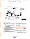
PROBLEMS
(SYMPTOMS)
POSSIBLE AREAS OF
MISADJUSTMENT(S)
RECOMMENDED
COURSE OF ACTION
If for any reason you do not understand the test procedures or are unable to perform the tests/repairs safely,
contact the Lincoln Electric Service Department for technical troubleshooting assistance before you proceed.
Call 1-888-935-3877.
CAUTION
The engine will not go to high idle
when a welding or auxiliary load
is applied. Engine idles up
normally and outputs are normal
when the engine switch is placed
in the “high” position.
1. Poor connection in weld circuit;
check cables, connectors, work
clamp and electrode holder.
Check that work clamp is
making a good connection to
the work piece.
2. Load too low to activate the idle
circuit. Plug in a device that
applies a load of 100 watts or
more.
NOTE: Some tools and devices
check for “good” power before
fully turning on. These devices
will require the machine to be
placed in the “high” position
before they will function.
1. Unplug P4/J4 connector and
measure the idle solenoid
resistance between leads
213B and 215A. it should
measure about 15 ohms.
Measure the resistance from
lead 213B or lead 215A to
chassis ground. Resistance
should be very high; 500,000
(500K) ohms or higher.
Replace the solenoid if the
resistance is significantly
different.
2. Reconnect P4/J4 and start the
machine placing the engine
switch in the high” position.
Plug in a 100-watt light bulb.
Check for AC voltage at leads
260 (J2-3) and 261 (J2-4). The
meter should read about 1.2
volts. If voltage is significantly
lower, replace the toroidal
current transformer.
3. If the above readings are
normal, replace the PC board.
No weld or auxiliary output –
Engine runs normally.
1. Make sure there is no load on
the machine. Disconnect all
cables and cords from the weld
output terminals and the
auxiliary receptacles. Check for
DC open circuit voltage (OCV)
(About 70 to 80 volts) at the
weld output terminals and check
for AC auxiliary voltage at the
120 and 240 VAC receptacles.
2. Check that circuit breakers are
not tripped.
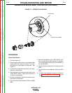
1. The brushes and slip rings may
be worn or faulty. Perform the
brush and slip ring service
procedure.
2. With the engine running, check
for battery voltage at the PC
board, J3-9 (lead #208A). If
voltage is not present, check
conductors and connection at
leads 208A, 208, and the
engine wiring leading to the
engine charging system. If the
connections are good, the
battery charging system may
be faulty. Contact a qualified
engine repair technician.
TROUBLESHOOTING AND REPAIR
F-8 F-8
OUTBACK® 185
Return to Section TOC Return to Section TOC Return to Section TOC Return to Section TOC
Return to Master TOC Return to Master TOC Return to Master TOC Return to Master TOC