


OUTPUT PROBLEMS
Observe Safety Guidelines detailed in the beginning of this manual.
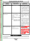
PROBLEMS
(SYMPTOMS)
POSSIBLE AREAS OF
MISADJUSTMENT(S)
RECOMMENDED
COURSE OF ACTION
If for any reason you do not understand the test procedures or are unable to perform the tests/repairs safely,
contact the Lincoln Electric Service Department for technical troubleshooting assistance before you proceed.
Call 1-888-935-3877.
CAUTION
The engine runs erratically or
stops running.
1. Check that the fuel valve is fully
open, and that there is
sufficient, fresh gasoline in the
tank.
2. The choke may be engaged.
Be sure the choke handle is
pushed in completely after the
engine has begun to warm up.
3. Be certain that the battery is
properly connected and
adequately charged, even if
using the recoil starter.
4. Check the engine oil level.
5. Check or replace the fuel filter.
6. Check or replace air filter.
7. Check spark plug; clean or
replace if necessary.
8. Observe the oil level indicator
light while cranking the engine.
If the light is blinking while
cranking the engine, the oil level
may be low, or the oil level
system may be faulty. Contact
the engine manufacturer.
9.Perform any additional
maintenance suggested in the
engine operator’s manual.
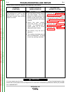
1. Check the idle solenoid and
engine carburetor linkage for
damage, excessive dirt, or
binding. If possible, perform
the engine RPM adjustment
procedure.
2. Place the engine switch in the
“stop” position, unplug engine
to welder harness connector
(P4/J4) located inside the
control box at the bottom left.
CAUTION: Disconnecting this
plug disables the normal engine
shut down function of the
engine switch. Reconnect
P4/J4 to shut the engine down.
3. Attempt to start the engine
using the recoil starter.
4. If the problem persists check for
faulty insulation at the brown
and brown/white wires
connecting P4/J4 to the engine
magneto. If the insulation is
good, contact a qualified engine
repair technician.
5. If the engine runs normally with
P4/J4 disconnected, check for
battery voltage between J3-10
(+) and J1-2 (-). If the voltage
is low or erratic, check
conductors and connections at
GND-G, lead #211, lead 209A,
and lead 230. Check the fuse,
fuse holder, and the engine
switch. Replace or repair any
defective leads or components.
6. If the voltage between J3-10 (+)
and J1-2 (-) is normal, check for
defective insulation on lead
212. If insulation is good,
replace PC board.
TROUBLESHOOTING AND REPAIR
F-6 F-6
OUTBACK® 185
Return to Section TOC Return to Section TOC Return to Section TOC Return to Section TOC
Return to Master TOC Return to Master TOC Return to Master TOC Return to Master TOC