


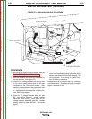
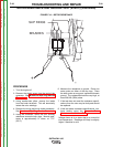
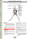
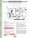
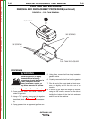

HIGH IDLE ADJUSTMENT
LOW IDLE ADJUSTMENT
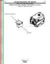
TOP VIEW OF ENGINE
FIGURE F.12 – HIGH AND LOW IDLE ADJUSTMENT
WELD BOOST SYSTEM TEST (continued)
PROCEDURE
1. Check that the CB4 circuit breaker is not tripped.
2. Check that the battery is fully charged and in
good condition.
3. Set the output dial to the Maximum position.
4. Start the engine and place the engine switch in
the High idle position.
5. Verify that the engine RPM is correct. See the
Engine RPM adjustment procedure.
6. Turn on the load bank and adjust to get a 165 to
190 Amp load.
7. Check engine RPM, it should not fall below 3300
RPM.
8. Read the DC voltage at the output terminals. If
the voltage is between 21 and 27, the boost sys-
tem is functioning normally.
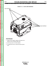
9. If the weld terminal voltage is low. Shut off the
engine and perform the Case Cover Removal
Procedure.
10. Start the engine and apply a load of about 80
to 100 Amps.
11. Check for AC voltage between leads 13 and 14
at the PC board. See wiring diagram.
12. If voltage is present, rotate the output control
knob and observe the voltage between leads
13 and 14. The voltage should rise and fall as
the output control is moved.
13. If the voltage at leads 13 and 14 is responding
as described above, the PC board is probably
defective.
14. If no significant voltage is detected at leads 13
and 14, and if the voltage does not respond to
changes to the output control knob setting,
check for a defective CB4 circuit breaker.
Check for poor connections or damaged wires
at leads 13, 13A and 14. If the breaker and
wires are good, the reactor is likely defective.
TROUBLESHOOTING AND REPAIR
F-36 F-36
OUTBACK® 185
Return to Section TOC Return to Section TOC Return to Section TOC Return to Section TOC
Return to Master TOC Return to Master TOC Return to Master TOC Return to Master TOC