


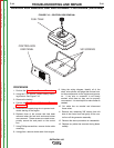

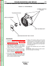


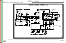
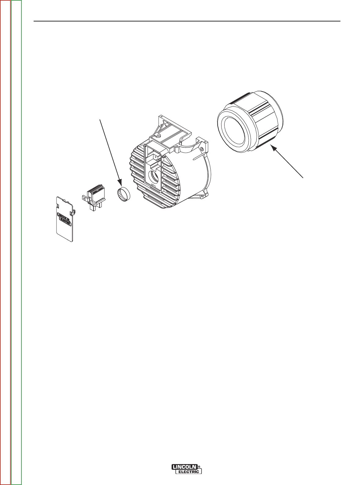
TOLERANCE RING
STATOR
FIGURE F.20 – STATOR LOCATION
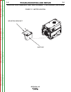
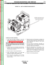
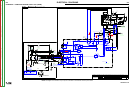
STATOR REMOVAL AND REPLACEMENT PROCEDURE (continued)
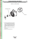
10. Check the air gap between the rotor and the
stator. Feeler gages are inserted between the
rotor and stator through the brush access
opening. A .010 gage should be able to pass
completely through the air gap and a .030
gage should not penetrate the air gap any far-
ther than any tapered portion on the end of the
gage.
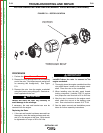
11. Reinstall the control box and fuel tank previ-
ously removed.
12. Replace the case wraparound cover.
TROUBLESHOOTING AND REPAIR
F-50 F-50
OUTBACK® 185
Return to Section TOC Return to Section TOC Return to Section TOC Return to Section TOC
Return to Master TOC Return to Master TOC Return to Master TOC Return to Master TOC