


THEORY OF OPERATION
E-3 E-3
OUTBACK® 185
ENGINE STARTING, PROTECTION
AND BATTERY CHARGING (contin-
ued)
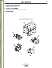
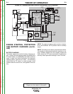
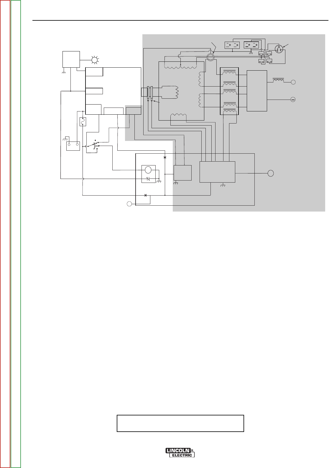
BATTERY CHARGING
The Kohler engine has a built-in battery charging sys-
tem. Output from the charging system is applied to the
PC board where it is stabilized by the battery and then
used to power the board electronics, the generator
flashing system, and the hour meter. The remaining
output exits the PC board, is routed through a fuse
located inside the control box, and applied to the bat-
tery.
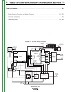
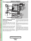
FIGURE E.3 - ENGINE STARTING, PROTECTION AND BATTERY CHARGING
NOTE: The engine charging system must be function-
al for the Outback® 185 to produce weld or auxiliary
output.
NOTE: The battery must remain connected at all times.
If the battery is disconnected while the machine is run-
ning, unstable voltage from the charging system will
likely cause the PC board electronics to malfunction
and may cause permanent damage to the PC board.
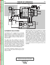
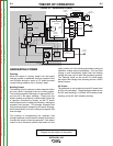
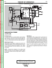
NOTE: Unshaded areas of Block Logic
Diagram are the subject of discussion
Return to Section TOC Return to Section TOC Return to Section TOC Return to Section TOC
Return to Master TOC Return to Master TOC Return to Master TOC Return to Master TOC
+
CB1
CB3
CB2
CB4
__
++
_
+
240 VAC
RECEPTACLE
ENGINE
OIL
LEVEL
MODULE
(KOHLER)
OIL LEVEL
INDICATOR
OIL LEVEL
SWITCH
IGNITION
STATOR
ROTOR
OFF
AUTO
HIGH
START
ALTERNATOR
IDLE
SOLENOID
SLIP
RINGS
AUXIIARY WINDINGS
WELD
WINDINGS
REACTOR
EXCITER
WINDING
CURRENT
SENSOR
120 VAC RECEPTACLES
BOOST
WINDING
OUTPUT
RECTIFIER
(2 PHASE)
CHOKE
OUTPUT
STUDS
BATTERY
ENGINE
SHUTDOWN
RELAY
HOUR
METER
FIELD / CONTROL PC BOARD
AUTOMATIC
IDLER
CIRCUIT
OUTPUT
CONTROL CIRCUIT
OUTPUT
CONTROL
10 AMP
FUSE
STARTER /
SOLENOID
BRUSHES