


STATOR SHORT CIRCUIT AND GROUND TEST (continued)
PROCEDURE
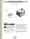
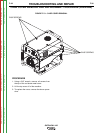
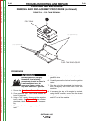
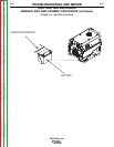
1. Perform Case Cover Removal Procedure.
2. Disconnect anything that may be connected to
the auxiliary receptacles or the weld output ter-
minals.
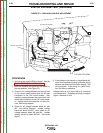
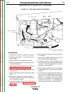
3. Disconnect and isolate GND-C lead from the
ground stud on the control panel front. See
wiring diagram.
4. Disconnect and isolate lead #5 from the neutral
stud on the control panel bottom. See wiring
diagram.
5. Disconnect the #7 and #9 leads from the PC
board.
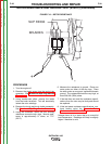
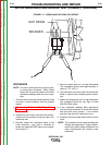
6. Using an ohmmeter, check the resistance
between chassis ground and each of the fol-
lowing points; resistance should read very high:
500,000 (500k) ohms minimum.
a) The #5 lead that had been disconnected from
the neutral stud. (This tests for a grounded
auxiliary winding.)
b) The #7 or #9 lead. (This tests for a ground-
ed exciter winding.)
c) W1 or W2 lead. (This tests for a grounded
weld winding.)
d) W3 or W4 lead. (This tests for a grounded
weld winding.)
If any of these readings are less than 500,000
(500k) ohms, check for grounded components or
wiring that remain connected to the stator, such as
circuit breakers, receptacles, output rectifier, reac-
tor, etc. See Wiring Diagram. If necessary, dis-
connect and isolate the stator leads as close to the
stator winding as possible. If the low resistance to
ground is determined to be in the stator windings,
the stator is defective and should be replaced.
7. If the stator is not grounded, check for short cir-
cuit connections between the windings that
should be isolated from each other.
8. Using an ohmmeter; check the resistance
between the following points. Resistance
should red very high, 500,000 (500k) ohms min-
imum.
a) The #5 lead that had been disconnected
from the neutral stud, and either lead #7 or
lead #9. (This checks for a connection
between the auxiliary power winding and
the excited winding.)
b) The #5 lead that had been disconnected
from the neutral stud, and lead W1 or W2.
(This checks for a connection between the
wire auxiliary power winding and one of
the weld windings.)
c) The #5 lead that has been disconnected from
the neutral stud, and lead W3 or W4. (This
checks for a connection between the auxiliary
power winding and the other weld winding.)
d) Lead #7 and lead W1 or W2. (This checks
for a connection between the exciter wind-
ing and one of the weld windings.)
e) Lead #7 and lead W3 or W4. (This checks
for a connection between the exciter wind-
ing and the other weld winding.)
If any of the above readings is less than 500,000
(500k) ohms, check for damaged, contaminated, or
shorted wiring, or defective components connected
to the stator windings. If necessary, disconnect
and isolate leads as close to the stator winding as
possible. See Wiring Diagram. If the low resis-
tance is determined to be between the windings
within the stator, the stator is defective and should
be replaced.
TROUBLESHOOTING AND REPAIR
F-34 F-34
OUTBACK® 185
Return to Section TOC Return to Section TOC Return to Section TOC Return to Section TOC
Return to Master TOC Return to Master TOC Return to Master TOC Return to Master TOC