


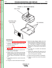

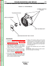


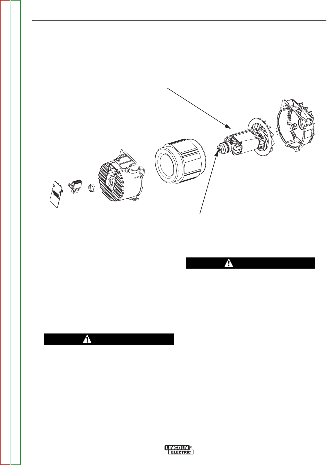
THROUGH BOLT
ROTOR
FIGURE F.21 – ROTOR LOCATION
ROTOR REMOVAL AND REPLACEMENT PROCEDURE (continued)
TROUBLESHOOTING AND REPAIR
F-52 F-52
OUTBACK® 185
Return to Section TOC Return to Section TOC Return to Section TOC Return to Section TOC
Return to Master TOC Return to Master TOC Return to Master TOC Return to Master TOC
PROCEDURE
1. Perform the Stator Removal Procedure.
2. Remove the long through-bolt from the bearing
end of the rotor. (An impact wrench works best
for removing this through-bolt). See Figure
F.21.
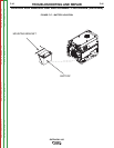
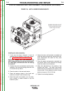
3. Remove the rotor from the engine crankshaft
using the Lincoln rotor-pulling tool. See instruc-
tions supplied with the tool.
Handle and store the rotor very carefully to
avoid damage to the windings.
If necessary, the cast end bracket can now be
removed from the engine.
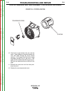
Replacing the Rotor
1. If the cast end bracket had been removed from
the engine, clean the mating surfaces and rein-
stall it on the engine at this time. Bolts should
be tightened to a torque of 22 to 24 ft-lbs.
It is highly recommended that a new bearing be
installed before the rotor is secured to the
engine crankshaft.
2. Thoroughly clean the engine crankshaft and the
rotor shaft where it mates to the engine crank-
shaft. Place the rotor on the crankshaft.
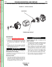
3. When installing rotor thru-bolt, apply thread-
locking compound, (Locktite 2760 or equiva-
lent) torque the rotor thru-bolt to 22 to 24 ft-lbs.
4. After the rotor is secured to the engine crank-
shaft, check the run-out at the bearing outer
race. Run out should not exceed .015” F.I.M.
5. See the stator removal and installation proce-
dures for further assembly instructions.
IMPORTANT
IMPORTANT