


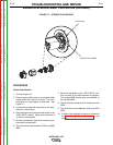
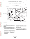


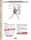

GENERATOR END BRACKET
BRUSH HOLDER ASSEMBLY
COVER
SCREWS (2)
LOCKING TABS
FIGURE F.5 – BRUSH HOLDER ASSEMBLY LOCATION
BRUSH AND SLIP RING SERVICE PROCEDURE (continued)
PROCEDURE
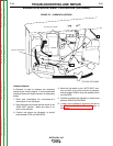
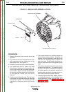
1. Remove the brush cover from the end of the
generator.
2. Pry outward at the top of the plastic brush cover
while depressing the two locking tabs at the
sides of the cover. See Figure F.5.
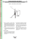
3. Remove the brush and brush holder assembly.
4. Use needle-nose pliers to remove the leads
from the brush terminals, and then use the 1/4”
nut driver to remove the two screws holding the
brush holder in place. The brush holder assem-
bly can now be pulled straight out from the end
of the generator toward the front of the
machine.
5. Examine brushes and slip rings. The slip rings,
brush holder, and brushes should be clean and
free from oil or grease. The brushes should be
making good, continuous contact with the slip
rings.
6. The brushes should be of sufficient length and
have adequate spring tension. Generally, the
brushes should be replaced if either brush has
less than 1/4” remaining before it reaches the
end of its travel. Spring tension should be suf-
ficient to hold the brushes firmly against the slip
rings.
7. The brushes should be removed from the brush
holder and be examined. The terminals should
be clean. The shunt, (braided lead connecting
the carbon brush to the terminal) should be in
good condition and firmly connected to the car-
bon brush and to the connection terminal.
8. If the slip rings are discolored, display evidence
of excessive sparking, or the brushes have
worn prematurely; these may be signs of a
grounded or shorted roter. Perform The Rotor
Resistance Test.
TROUBLESHOOTING AND REPAIR
F-20 F-20
OUTBACK® 185
Return to Section TOC Return to Section TOC Return to Section TOC Return to Section TOC
Return to Master TOC Return to Master TOC Return to Master TOC Return to Master TOC