


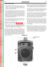
INSTALLATION
A-5 A-5
V160-S & -T
Return to Section TOC Return to Section TOC Return to Section TOC Return to Section TOC
Return to Master TOC Return to Master TOC Return to Master TOC Return to Master TOC
• Ranger 250,305
• Commander 300, 400, & 500
Many engine drives do not meet these conditions (eg
Miller Bobcats, etc). Operation of the Invertec V160-S
is not recommended on engine drives not conforming
to these conditions. Such combinations may overvolt-
age the Invertec V160-S power source.
OUTPUT CONNECTIONS
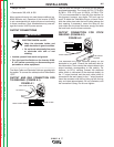
ELECTRIC SHOCK can kill.
• Keep the electrode holder and
cable insulation in good condition.
• Do not touch electrically live parts
or electrode with skin or wet
clothing.
• Insulate yourself from work and ground.
• Turn the input line Switch on the Invertec V160-
S “off” before connecting or disconnecting out-
put cables or other equipment.
-----------------------------------------------------------
The Work Cable and Electrode Cable are supplied with
the welder. To connect the cables,turnthePowerSwitch
“OFF”.
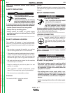
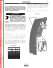
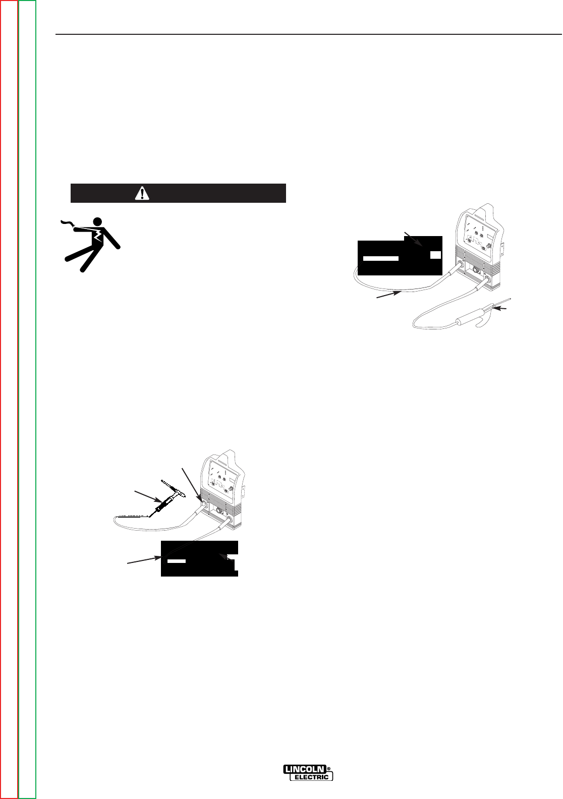
OUTPUT AND GAS CONNECTION FOR
TIG WELDING (FIGURE A.1)
This unit does not include a TIG torch, but one may be
purchased separately. The Lincoln (K1781-7 PTA-9FV,
K1782-11 PTA-17FV) and (K1782-6, K1782-8 PTA-
17V) are recommended for use with this machine for
this purpose; however, any similar TIG torch can be
used. To attach the Twist-Mate Plug to a Lincoln Torch,
slide the rubber boot onto the torch cable (enlarge the
boot opening if necessary), screw the fitting on the
torch cable into the brass connector snugly and slide
the boot back over the brass connector.
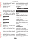
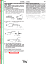
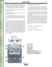
OUTPUT CONNECTION FOR STICK
WELDING (FIGURE A.2)
First determine the proper electrode polarity for the
electrode to be used. Consult the electrode data for
this information. Then connect the output cables to the
output terminals corresponding to this polarity. For
instance, for DC(+) welding, connect the electrode
cable (which is connected to the electrode holder) to
the “+” output terminal and the work cable (which is
connected to the work clamp) to the “-” output terminal.
Insert the connector with the key lining up with the key
way, and rotate approximately 1/4 turn clockwise; until
the connection is snug. Do not over tighten.
FIGURE A.2
WORK CLAMP
WORK CABLE
ELECTRODE
HOLDER
WARNING
WORK CLAMP
WORK CABLE
TIG TORCH
GAS HOSE NOZZLE
FIGURE A.1