


OPERATION
BB-5 BB-5
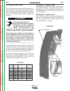
V160-S & -T
Return to Section TOC Return to Section TOC Return to Section TOC Return to Section TOC
Return to Master TOC Return to Master TOC Return to Master TOC Return to Master TOC
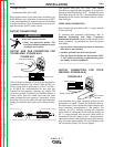
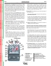
12. Postflow Control: In the TIG welding modes, this
control knob will adjust the shielding gas postflow time
from 0.5 to 30 seconds. (The preflow time is always
0.5 seconds.) In Stick welding mode, this function is
not used.
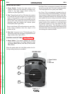
13. Digital Display: This meter displays the preset weld-
ing current before welding and the actual welding cur-
rent during welding. Like the output current control,
the function of the meter is changed if a remote con-
trol is connected.
14. Pulsing Mode Switch: In the TIG welding modes,
this switch turns the pulsing function ON and controls
the pulsing frequency range (20Hz or 300Hz). In Stick
welding mode, this function is not used.
15. Pulsing LED: This indicator shows the pulsing fre-
quency when pulsing is turned ON. With this indica-
tion, the operator can adjust the frequency to the
desired value before welding. (Note: At higher fre-
quencies the LED blinks very fast and seems to be
continuously ON however it is pulsing.) If pulsing is
turned OFF or if the machine is in Stick welding mode,
the indicator will be OFF.
16. Pulsing Frequency Control: When the pulsing func-
tion is ON, this control knob will adjust the pulsing fre-
quency. The pulsing frequency adjustment range is
0.2 - 20Hz or 3 - 300Hz depending on the Pulsing
Mode Switch position.
17. Background Current Control: When the pulsing
function is ON, this control knob will adjust the pulsing
background current. This is the current during the low
portion of the pulse waveform; it can be adjusted from
10% to 90% of the welding current.
TRIGGER MODE SEQUENCES
For the V160-T, TIG welding can be done in either the 2-
step or 4-step mode which is selected with the Trigger
Mode Switch. DIP Switch functions are set by the factory.
For adjustments on DIP Switch settings and functions see
DIP SWITCH FUNCTIONS in this Operations Section.
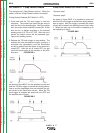
2-Step Sequence
Note: 2-Step works with either an Arc Start Switch (for
output triggering only, current control is at machine) or
with a Foot or Hand Amptrol™ (for both remote output
triggering and current control). 2-Step used with Arc Start
Switch is referenced in following sequence.
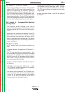
1. Press and hold the Arc Start Switch to start the
sequence.
The machine will open the gas valve to start the flow of
the shielding gas. After a 0.5 second preflow time to
purge air from the torch hose, the output of the machine
is turned ON. At this time the arc can be started.
After the arc is started the output current will be
increased to the welding current. The time for this
increase or upslope is presettable. The default is 0.5
seconds.
2. Release the Arc Start Switch to stop welding.
The machine will now decrease the output current at
a controlled rate or downslope time, until the
Start/Crater current is reached and the output of the
machine is turned OFF. The downslope time is
adjusted by the Downslope Parameter.
After the arc is turned OFF, the gas valve will remain
open to continue the flow of the shielding gas to the
hot electrode and work piece. The duration of this
postflow shielding gas is adjusted by the Postflow
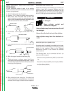
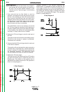
Parameter. This operation is shown in (2 step dia-
gram 1).
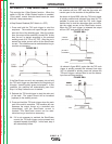
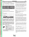
Possible variations of this standard sequence is shown
below. It is possible to press and hold the TIG torch
trigger a second time during downslope to restart. After
the trigger is pressed the output current will increase to
the welding current. This operation is shown in (2 step
diagram 2).
2 Step Diagram 1
2 Step Diagram 2