


TROUBLESHOOTING & REPAIR
F-32 F-32
V160-S & -T
Return to Section TOC Return to Section TOC Return to Section TOC Return to Section TOC
Return to Master TOC Return to Master TOC Return to Master TOC Return to Master TOC
Inverter Board
MAIN IGBT INVERTER BOARD REMOVAL AND REPLACEMENT
PROCEDURE
(continued)
REMOVAL PROCEDURE
1. Remove input power to the V160-S/T.
2. Perform the Case Cover Removal
Procedure.
3. Perform the Capacitor Discharge
Procedure.
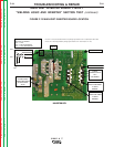
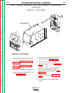
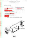
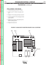
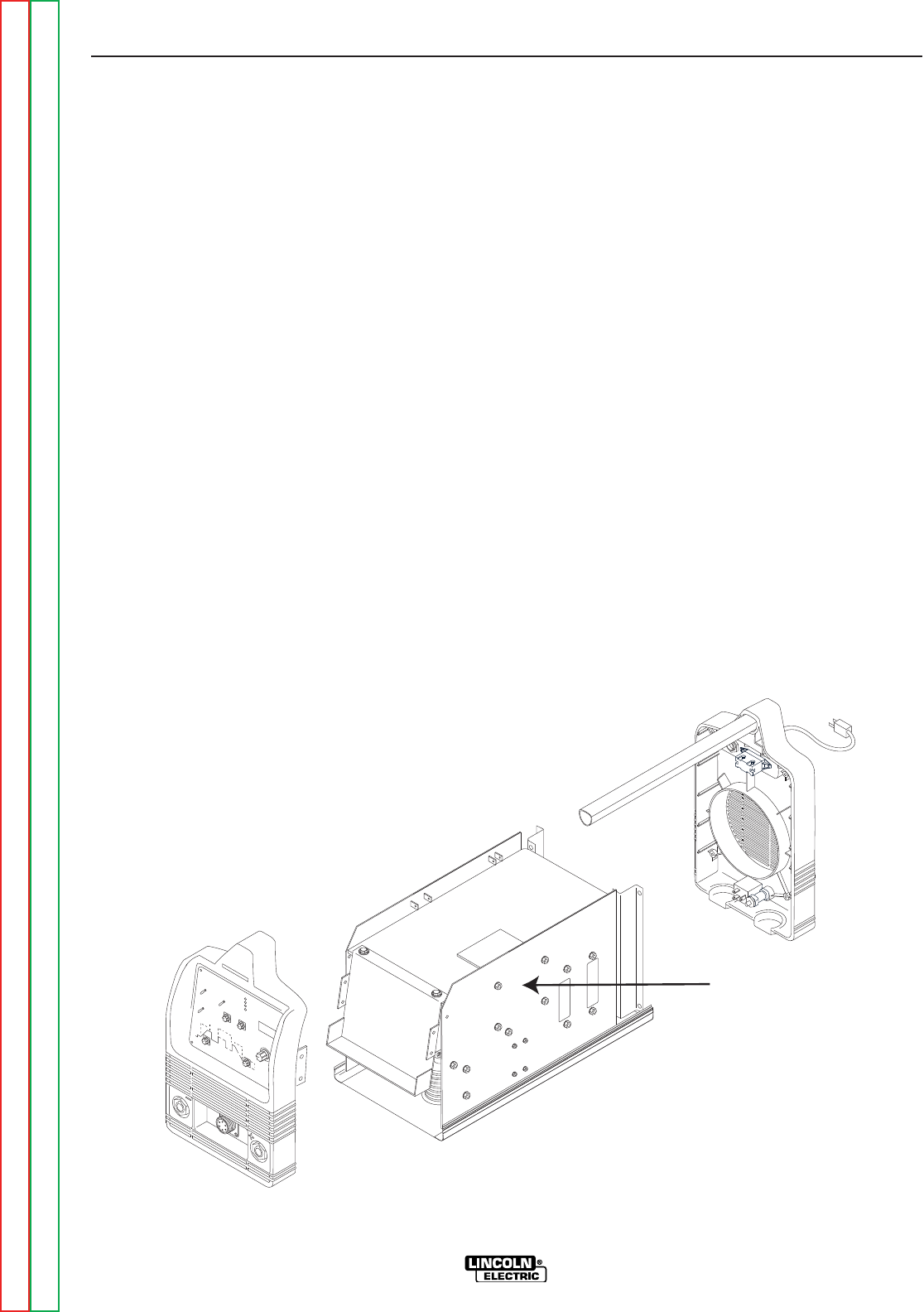
4. Locate the Inverter Board. See Figure F.17.
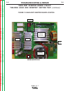
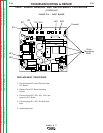
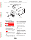
5. Using a 7mm nutdriver remove the four P.C.
Board mounting screws. See Figure F.19.
6. Label and disconnect leads DC-, DC+ and
plug JP1 from the top of the Inverter Board.
See Figure F.18.
7. Using a 10mm nutdriver remove the two
bolts connecting the P.C. Board to heavy
leads. See Figure F.19.
8. The Board may now be tilted forward to
gain access to the ground lead.
9. Label ground lead position and disconnect.
10. Remove and replace Main Input P.C.
Board.
FIGURE F.17 MAIN IGBT INVERTER BOARD LOCATION