


OPERATION
BB-4 BB-4
V160-S & -T
Return to Section TOC Return to Section TOC Return to Section TOC Return to Section TOC
Return to Master TOC Return to Master TOC Return to Master TOC Return to Master TOC
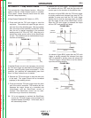
When the mode switch is in the Lift TIG position, the stick
welding functions are disabled and the machine is ready
for Lift TIG welding. Lift TIG is a method of starting a TIG
weld by first pressing the TIG torch electrode on the work
piece in order to create a low current short circuit. Then,
the electrode is lifted from the work piece to start the TIG
arc. After machine output is triggered ON, the arc must be
started within 6.5 seconds or output will turn OFF and trig-
ger sequence must be restarted.
When the mode switch is in the HF TIG position, the stick
welding functions are disabled and the machine is ready
for HF TIG welding. During the HF TIG mode, the TIG arc
is started by HF without pressing the electrode on the
work piece. After triggering output ON, the HF (and out-
put) used for starting the TIG arc will remain ON for 6.5
seconds. If the arc is not started in this time limit, the trig-
ger sequence must be restarted.
5. Trigger Mode Switch: This switch changes between 2-
step and 4-step trigger sequences. For an explanation of
these trigger sequences refer to the Trigger Mode
Sequences following Controls and Settings.
6. Power LED: This indicator will blink on and off when
the machine is first turned on. After approximately 2
seconds it will stop blinking and remain on to signal that
the machine is ready.
The indicator will also blink dur-
ing over current conditions when operating on 115V
input.
7. Thermal LED: This indicator will turn on when the
machine is overheated and the output has been disabled.
This normally occurs when the duty cycle of the machine
has been exceeded. Leave the machine on to allow the
internal components to cool. When the indicator turns off,
normal operation is again possible.
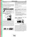
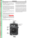
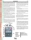
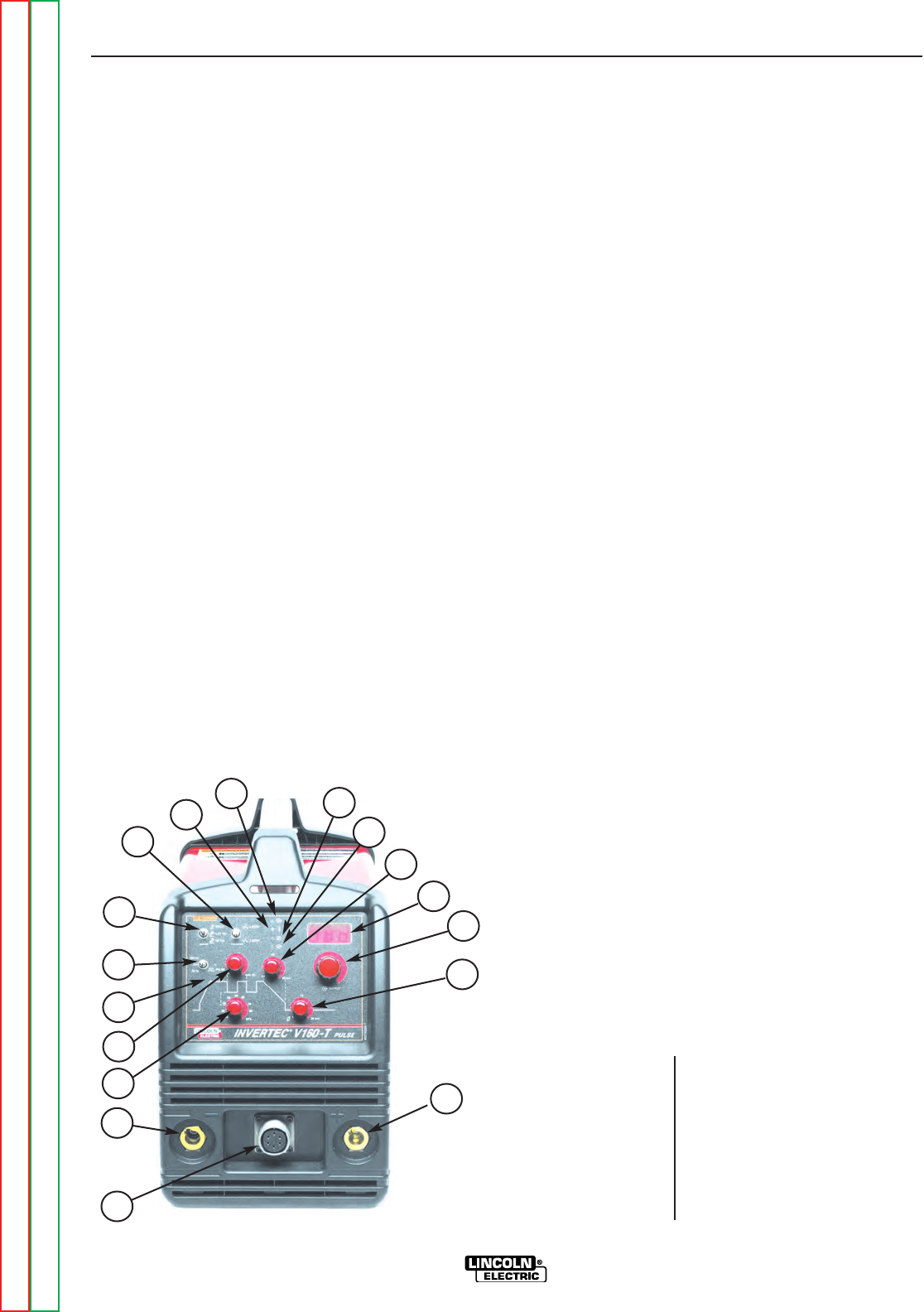
4. Mode Switch
5. Trigger Mode Switch
6. Power LED
7. Thermal LED
8. Remote LED
9. Output LED
10. Output Current Control
11. Downslope Control
12. Postflow Control
13. Digital Display
8. Remote LED: This indicator will turn ON when a
remote control is connected to the machine via the
remote control connector. Using a remote control will
change the function of the output current control., refer
to the output current control section below. (Note:
When K814 Arc Start Switch is connected to remote
connector, remote LED will remain OFF).
9. Output LED: This indicator turns on when the output of
the machine is on.
• In the stick welding mode, the output of the machine is
automatically turned ON.
• For both of the TIG welding modes, the output of the
machine is turned ON and OFF by an Arc Start Switch
or Hand/Foot Amptrol attached to the Remote Control
Connector. (See #4 - Mode Switch - above for details
on output triggering for TIG arc starting).
10. Output Current Control: This controls the output or
welding current of the machine.
The function of this control knob is changed if a remote
control is connected. If the Remote LED is ON, this indi-
cates that a remote control is connected and the function
of the output current control will be:
• Stick Welding Mode: The remote control will adjust the
output current of the machine from 5 to 160A. The
output current control knob on the display panel is not
used.
• TIG Welding Modes: The maximum output current of
the machine is set by the output current control knob.
The remote control then adjusts the output current
from the minimum output (5A) to the value set by the
output current control knob. For example, if the output
current control knob on the machine is set to 100A
then the remote control will adjust the output current
from a minimum of 5A to a maximum of 100A.
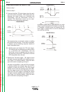
11. Downslope Control: In the TIG welding modes, this
control knob will adjust the downslope time from 0.5 to
20 seconds. (The default upslope time is 0.5 sec-
onds.) Refer to the trigger sequence section below to
understand how downslope is activated. In Stick weld-
ing mode, this function is not used.
FIGURE BB.2
5
14
15
16
17
19
18
20
4
6
8
9
11
13
10
12
7
14. Pulse Mode Switch
15. Pulse LED
16. Pulse Frequence Control
17. Background Current Control
18. Electrode Connection (Negative)
19. Remote Control Connector
20. Electrode Connection (Positive)