


TROUBLESHOOTING & REPAIR
F-36 F-36
V160-S & -T
Return to Section TOC Return to Section TOC Return to Section TOC Return to Section TOC
Return to Master TOC Return to Master TOC Return to Master TOC Return to Master TOC
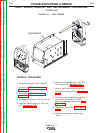
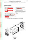
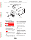
DISPLAY
BOARD
RED
CAP
6MM NUT & WASHER
C
ONTROL
KNOB
FOUR 7MM
MOUNTING
SCREWS
FOUR
2.5 MM
ALLEN
BOLTS
DISPLAY BOARD REMOVAL AND REPLACEMENT PROCEDURE
(continued)
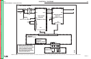
FIGURE F.20 – DISPLAY BOARD LOCATION
REMOVAL PROCEDURE
1. Remove input power to the V160-S/T.
2. Perform the Case Cover Removal
Procedure.
3. Perform the Capacitor Discharge
Procedure.
4. Locate the Display Board. See Figure
F.20.
5. Gently place machine on its side.
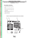
6. Using a 7mm nutdriver remove the three
casefront mounting screws located on
the bottom of the machine. See Figure
F.21.
7. Using a 7mm nutdriver remove the two
casefront mounting screws (four total) on
either side of the machine. See Figure
F.20.
8. The casefront may now be gently pulled
forward to gain access to display board
mounting bolts.
9. Using a thin knife blade or small flathead
screwdriver carefully remove the red
caps on the 5 control knobs located on
the front of the machine. See Figure
F.20.
10. Using a 6mm nutdriver remove the nut
and associated washers located
beneath the previously removed red
caps on the control knobs. See Figure
F.20.
11. Remove control knobs.
12. Using a 2.5mm allen wrench remove
the four display board mounting bolts
located at corners of board. Note
washer position for replacement. See
Figure F.20.
13. Disconnect plugs J1 and JP1 from the
display board.
14. Remove and replace display board.