


THEORY OF OPERATION
EE-4 EE-4
V160-S & -T
Return to Section TOC Return to Section TOC Return to Section TOC Return to Section TOC
Return to Master TOC Return to Master TOC Return to Master TOC Return to Master TOC
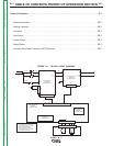
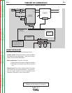
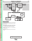
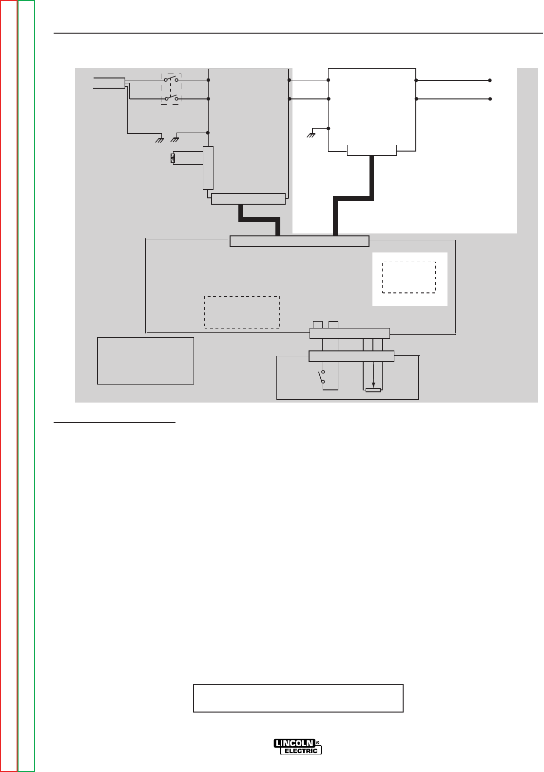
NOTE: Unshaded areas of Block Logic
Diagram are the subject of discussion
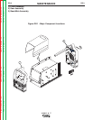
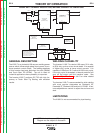
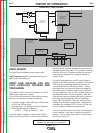
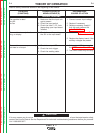
FIGURE EE.4 – INVERTER BOARD
INVERTER BOARD
The inverter board includes the following circuits:
- Inverter circuit: Transforms the DC current at 80KHz
and feeds the main transformer. The current is regu-
lated via Pulse Width Modulation
- Main transformer: It has two functions:
1) gives the correct output voltage for welding
2) Insulates the operator side from the output
line
- Output circuit: The output diodes rectify the output
the current from the main transformer. The choke fil-
ters the output current.The shunt provides output
feedback information to the control board.
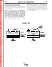
INVERTER BOARD
W05X0190
(SCHEMATIC X0190)
GND
DC-
DC+
W1
W2
INPUT BOARD
W05X0250
(SCHEMATIC X0203)
Y/G
BLACK
RED
W1DC-DC-
+
-
JP1
JP1
JP2
G
ND
A
C2
AC1
BROWN
BLUE
BLACK
WHITE
S1
1
3
4
2
DC+
DC-A
115/230/1/50/60
V
ac
GREEN
FAN
J1
W
ELD CONTROLLER
W
05X0233
(SCHEMATIC X0233)
DISPLAY BOARD
W05X0245
(
SCHEMATIC X0245)
JP1
CW
REMOTE
CONNECTOR
W
ARNING HIGH VOLTAGE CAN KILL
• Do not operate with coers removed.
• Disconnect input power by unplugging
power cord before servicing.
• Do not touch electrically live parts.
• Only qualified persons should install,
use or service this machine
1
2
3
6
1 2 3 4 5 6 7 8 9 10 11 12 13 14 15 16
1 2 3 4 5 6 7 8 9 10
26 25 24 23 22 21 20 19 18 17 16 15 14 13 12 11 10 9 8 7 6 5 4 3 2 1
1 2 3 4 5 6 7 8
D E C B A
METER BOARD
W05X0207
(
SCHEMATIC X0207)