


TROUBLESHOOTING & REPAIR
F-33 F-33
V160-S & -T
Return to Section TOC Return to Section TOC Return to Section TOC Return to Section TOC
Return to Master TOC Return to Master TOC Return to Master TOC Return to Master TOC
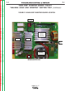
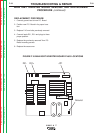
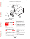
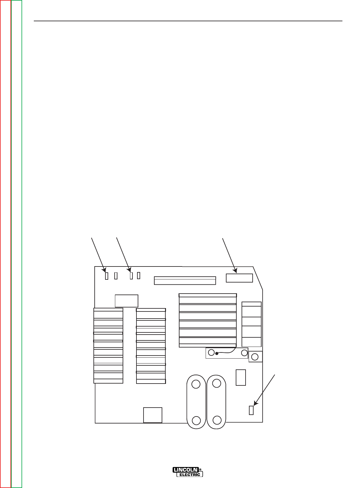
JP1
DC-
DC+
Ground
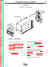
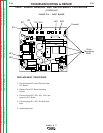
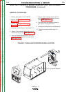
MAIN IGBT INVERTER BOARD REMOVAL AND REPLACEMENT
PROCEDURE
(continued)
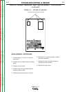
REPLACEMENT PROCEDURE
1. Connect ground lead to new P.C. Board
2. Position new P.C. Board in its proper loca-
tion.
3. Replace 2 10 mm bolts previously removed.
4. Connect leads DC-, DC+ and plugs to there
proper position.
5. Replace the previously removed 7mm P.C.
Board mounting screws.
6. Replace the case cover.
FIGURE F.18 MAIN IGBT INVERTER BOARD PLUG LOCATIONS