


TROUBLESHOOTING & REPAIR
F-37 F-37
V160-S & -T
Return to Section TOC Return to Section TOC Return to Section TOC Return to Section TOC
Return to Master TOC Return to Master TOC Return to Master TOC Return to Master TOC
7
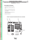
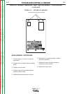
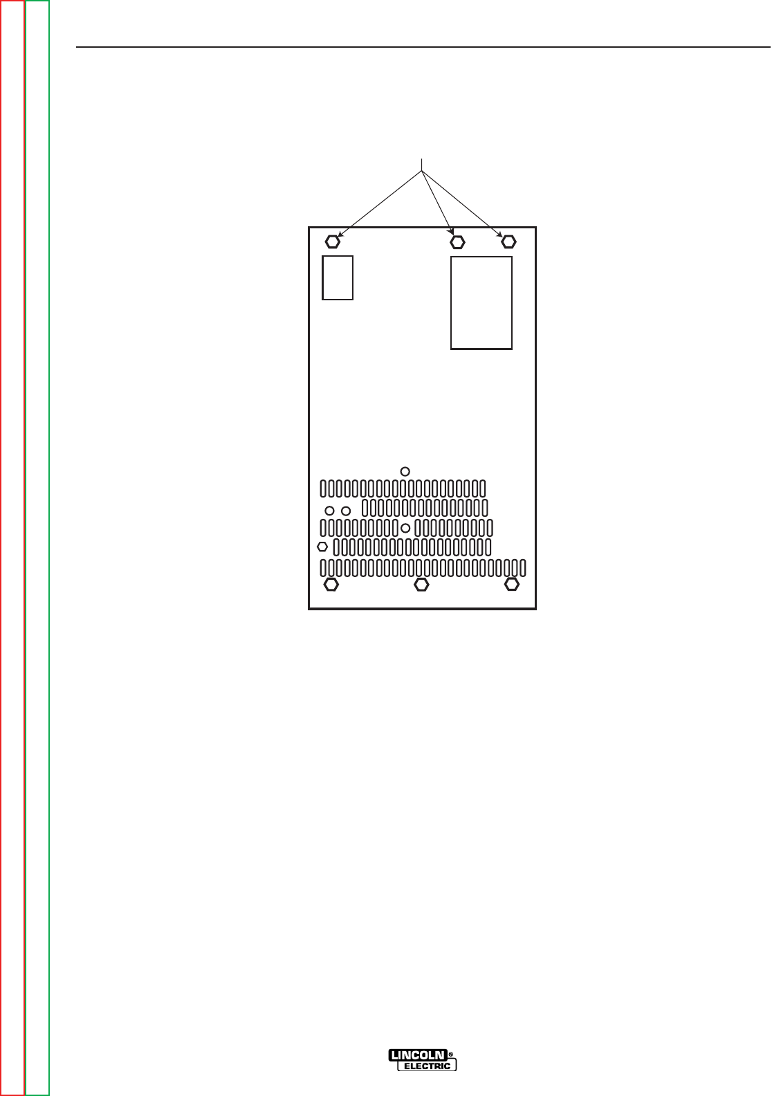
MM CASEFRONT MOUNTING SCREWS
DISPLAY BOARD REMOVAL AND REPLACEMENT PROCEDURE
(continued)
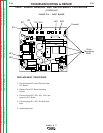
FIGURE F.21 – BOTTOM OF MACHINE
REPLACEMENT PROCEDURE
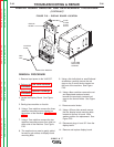
1. Connect plugs J1 and JP1 to new dis-
play board.
2. Replace the four display board mounting
bolts.
3. Replace control knobs.
4. Replace nuts and associated washers
securing control knobs.
5. Replace previously removed red caps.
6. Replace the 4 mounting screws on either
side of the machine.
7. Replace the three mounting screws on
the bottom of the machine.
8. Replace the case cover.