


THEORY OF OPERATION
EE-3 EE-3
V160-S & -T
Return to Section TOC Return to Section TOC Return to Section TOC Return to Section TOC
Return to Master TOC Return to Master TOC Return to Master TOC Return to Master TOC
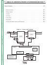
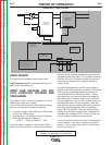
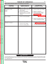
NOTE: Unshaded areas of Block Logic
Diagram are the subject of discussion
INPUT BOARD
The input board includes the following circuits:
High Frequency circuit: It generates the high volt-
age to start the welding arc
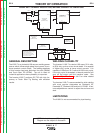
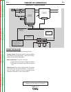
INPUT LINE VOLTAGE, FAN CIR-
CUIT, AUXILIARY VOLTAGE AND
PRECHARGE
The Invertec V160-T can be connected to a 115V or
230V single phase input voltage.
This unit can also connect to engine driven genera-
tors but it must follow the below conditions:
• Vac peak voltage: below 250V (for 115Vac input)
or 410V (for 230Vac input).
• Vac frequency: in the range of 50 and 60 Hertz.
• RMS voltage of the AC waveform:
V160-T: 115Vac or 230Vac +/- 10%
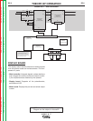
The initial power is applied to the Invertec V160-T
directly on the input board. A line switch located on
the back of the machine supplies the logic part that
manages machine functions. The voltage is after rec-
tified by the input on the input rectifier on the input
board and the resultant DC voltage is applied at
inverter Pcb’s.
During the precharge time the DC input voltage is
applied to the filter capacitors (located on the inverter
Pcb) through a precharge resistances (located on
input board) that limit the charge current. During
precharge time, an automatic system (manages by
reconnect board mounted on the input board) sets
the input board for 115V or 230V working mode (volt-
age duplicator when 115Vac is applied). After this
time the start relays go closed and they by-pass the
precharge resistances (there are two precharge
relays, RL1B and RL4B). The input voltage is also
applied to an auxiliary voltage circuit, that gives the
necessary low voltages (+15V, -5V and +5V) for the
control / display board and inverter board.
The fan is activated when the power is first supplied
to the machine. It will stay on as long as output is
present. The fan shuts down after 5 minutes when
the output is shut off.
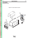
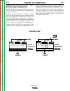
FIGURE EE.3 – INPUT BOARD
I
NVERTER BOARD
W05X0190
(SCHEMATIC X0190)
GND
DC-
DC+
W1
W
2
INPUT BOARD
W
05X0250
(SCHEMATIC X0203)
Y/G
BLACK
RED
W1DC-DC-
+
-
JP1
JP1
JP2
GND
AC2
AC1
BROWN
BLUE
BLACK
WHITE
S
1
1
3
4
2
DC+
DC-A
115/230/1/50/60
Vac
GREEN
FAN
J1
WELD CONTROLLER
W
05X0233
(SCHEMATIC X0233)
DISPLAY BOARD
W05X0245
(SCHEMATIC X0245)
JP1
CW
REMOTE
CONNECTOR
WARNING HIGH VOLTAGE CAN KILL
•
Do not operate with coers removed.
• Disconnect input power by unplugging
power cord before servicing.
• Do not touch electrically live parts.
• Only qualified persons should install,
use or service this machine
1
2
3
6
1 2 3 4 5 6 7 8 9 10 11 12 13 14 15 16
1 2 3 4 5 6 7 8 9 10
26 25 24 23 22 21 20 19 18 17 16 15 14 13 12 11 10 9 8 7 6 5 4 3 2 1
1 2 3 4 5 6 7 8
D E C B A
METER BOARD
W
05X0207
(SCHEMATIC X0207)