


OPERATION
BB-3 BB-3
V160-S & -T
Return to Section TOC Return to Section TOC Return to Section TOC Return to Section TOC
Return to Master TOC Return to Master TOC Return to Master TOC Return to Master TOC
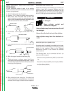
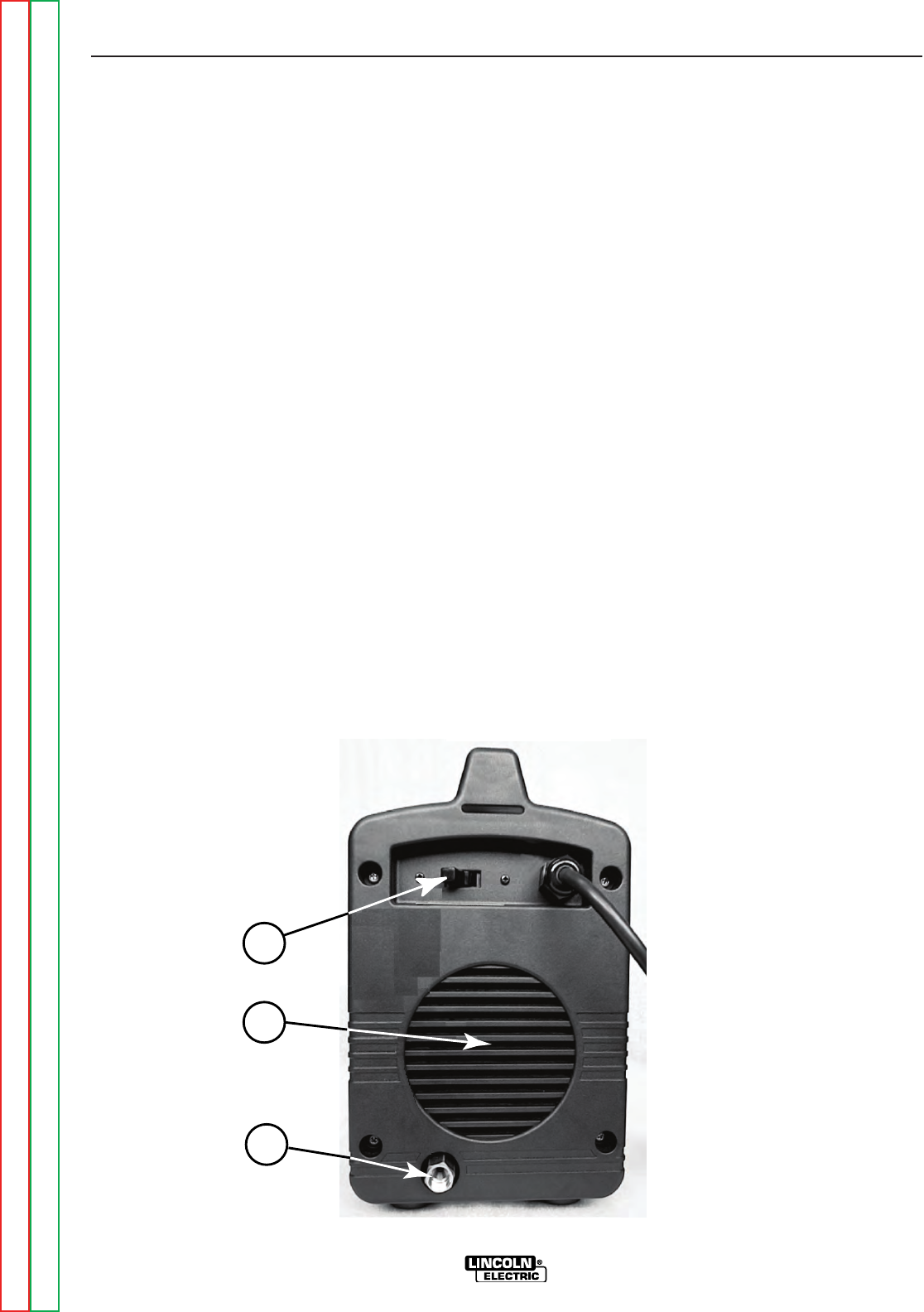
REAR CONTROL PANEL
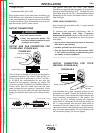
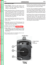
1. Power Switch: Controls the input power to the
machine. Make sure the machine is properly con-
nected to the input supply before turning the
machine on.(See Figure BB.1)
2. Fan: The cooling fan will turn ON when the machine
is turned ON and it will continue to run whenever the
output of the machine is ON. If the output of the
machine is OFF for more than five minutes, the fan
will turn OFF. This reduces the amount of dirt that is
deposited inside the machine and reduces power
consumption.(See Figure BB.1)
Refer to the Output LED section below for more infor-
mation about conditions when the output of the
machine is ON.
3. Gas Inlet: Connector for the TIG shielding gas. The
gas source must have a pressure regulator and flow
gage installed.(See Figure BB.1)
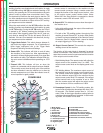
CONTROLS AND SETTINGS (See Figure BB.2)
4. Mode Switch: This switch changes the welding
modes of the machine. The V160-T has three weld-
ing modes: Stick (SMAW), Lift TIG (GTAW) and HF
TIG (GTAW).
When the mode switch is in the Stick position, the fol-
lowing welding features are enabled:
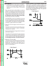
• Hot Start: This is a temporary increase in the output
current during the start of the stick welding process.
This helps ignite the arc quickly and reliably.
• Arc Force: This is a temporary increase in the out-
put current during normal stick welding. This tempo-
rary increase in output current is used to clear inter-
mittent connections between the electrode and the
weld puddle that occur during normal stick welding.
• Anti-Sticking: This is a function which decreases the
output current of the machine to a low level when
the operator makes an error and sticks the elec-
trode to the work piece. This decrease in current
allows the operator to remove the electrode from the
electrode holder without creating large sparks which
can damage the electrode holder.
1
2
3
FIGURE BB.1
1. Power Switch
2. Fan
3. Gas Inlet