


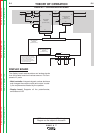
Keeping these contributing factors in mind, installing
equipment per the following instructions should mini-
mize problems.
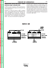
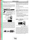
1. Keep the welder power supply lines as short as pos-
sible and enclose as much of them as possible in
rigid metallic conduit or equivalent shielding for a
distance of 50ft. (15.2m). Both ends of the conduit
should be connected to a driven ground and the
entire length should be continuous.
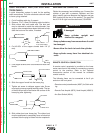
2. Keep the work and electrode leads as short as pos-
sible and as close together as possible. Lengths
should not exceed 25ft. (7.6m). Tape the leads
together when practical.
3. Be sure the torch and work cable rubber coverings
are free of cuts and cracks that allow high frequen-
cy leakage. Cables with high natural rubber content,
such as Lincoln Stable-Arc
®
better resist high fre-
quency leakage than neoprene and other synthetic
rubber insulated cables.
4. Keep the torch in good repair and all connections
tight to reduce high frequency leakage.
5. The work terminal must be connected to a ground
within ten feet of the welder, using one of the follow-
ing methods.
a) A metal underground water pipe in direct con-
tact with the earth for ten feet or more.
b) A 3/4” (19mm) galvanized pipe or a 5/8”
(16mm) solid galvanized iron, steel or copper
rod driven at least eight feet into the ground.
The ground should be securely made and the
grounding cable should be as short as possible
using cable of the same size as the work cable, or
larger. Grounding to the building frame electrical
conduit or a long pipe system can result in re-radi-
ation, effectively making these members radiating
antennas.
6. Keep all panels securely in place.
7. All electrical conductors within 50 ft (15.2m) of the
welder should be enclosed in grounded, rigid metal-
lic conduit or equivalent shielding. Flexible metallic
conduit is generally not suitable.
8. When the welder is enclosed in a metal building,
several earth driven electrical grounds connected
(as in 5 (b) above) around the periphery of the build-
ing are recommended.
Failure to observe these recommended installation
procedures can cause radio or TV interference prob-
lems.
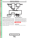
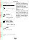
INPUT CONNECTIONS
ELECTRIC SHOCK can kill.
• Have a qualified electrician install
and service this equipment.
• Disconnect input power by removing
plug from receptacle before working
inside V160-T. Allow machine to sit
for 5 minutes
minimum to allow the
power capacitors to discharge
before working inside this equip-
ment.
• Do not touch electrically hot parts.
-----------------------------------------------------------------------
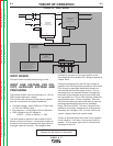
GROUND CONNECTION
The frame of the welder must be
grounded. A ground terminal marked
with the symbol is located on the under
panel for this purpose. See your local
and national electrical codes for proper
grounding methods.
The grounding is supplied in the input cord, it is
important that the Supply Receptacle Ground con-
nection is connected.
-----------------------------------------------------------------------
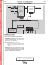
This installation should be performed by a quali-
fied electrician to ensure correct connections of
the leads to the plug spades.
• The electrical system must be made by skilled
technicians with the specific professional and
technical qualifications and in compliance with
the regulations in force in the country where the
equipment is installed.
• The welding power source supply cable is pro-
vided with a green or yellow/green wire that must
ALWAYS be earthed. This green or yellow/green
wire must NEVER be used with other voltage con-
ductors.
• lnstall only plugs that are corresponding to safe-
ty regulations.
------------------------------------------------------------------------
WARNING
CAUTION
WARNING
INSTALLATION
AA-4 AA-4
V160-S & -T
Return to Section TOC Return to Section TOC Return to Section TOC Return to Section TOC
Return to Master TOC Return to Master TOC Return to Master TOC Return to Master TOC