


106
APPENDIX
Appendix1 For customers replacing the
conventional model with this
inverter
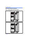
Appendix1.1 Replacement of the FR-A740 series
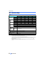
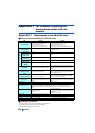
Difference and compatibility with FR-A740 series
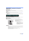
Installation precautions
• Removal procedure of the front cover is different. (Refer to page 15.)
• Plug-in options of the FR-A700 series are not compatible.
• Operation panel (FR-DU07) cannot be used.
Item FR-A740 FR-A842
Control method
V/F control
Advanced magnetic flux vector control
Real sensorless vector control
Vector control (with plug-in option used)
PM sensorless vector control (IPM motor)
V/F control
Advanced magnetic flux vector control
Real sensorless vector control
Vector control (with plug-in option used)
PM sensorless vector control (IPM motor/SPM motor)
Added functions
-
USB host function
Safety stop function
etc.
Maximum output frequency
V/F control
400 Hz 590 Hz
Advanced
magnetic flux
vector control
120 Hz 400 Hz
Real sensorless
vector control
120 Hz 400 Hz
Vector control
120 Hz 400 Hz
PM sensorless
vector control
(MM-CF)
300 Hz 400 Hz
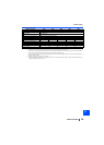
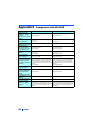
PID control
Turn the X14 signal ON to enable PID control.
The X14 signal does not need to be assigned. (PID control
is available by the Pr.128 setting.)
The PID pre-charge function and dancer control are
added.
Automatic restart after
instantaneous power
failure
Turn the CS signal ON to restart.
CS signal assignment not required. (Restart is enabled
with the Pr.57 setting only.)
Number of motor poles
V/F control switching
The V/F switchover (X18) signal is valid when
Pr.81 = "12 to 20 (2 to 10 poles)".
Pr.81= "12 (12 poles)"
X18 is valid regardless of the Pr.81 setting. (The Pr.81
settings "14 to 20" are not available.)
PTC thermistor input
Input from the terminal AU
(The function of the terminal AU is switched by a
switch.)
Input from the terminal 2.
(The function of the terminal 2 is switched by the Pr.561
setting.)
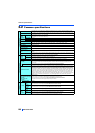
USB connector B connector Mini B connector
Control circuit terminal block Removable terminal block (screw type) Removable terminal block (spring clamp type)
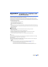
Terminal response level
The FR-A800's I/O terminals have better response level than the FR-A700's terminals. By setting Pr.289
Inverter output terminal filter and Pr.699 Input terminal filter, the terminal response level can be
compatible with that of FR-A700. Set to approximately 5 to 8 ms and adjust the setting according to the
system.
PU
FR-DU07 (4-digit LED)
FR-PU07
FR-DU08 (5-digit LED)
FR-PU07 (Some functions, such as parameter copy, are
unavailable.)
FR-DU07 is not supported.
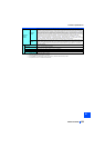
Plug-in option Dedicated plug-in options (not interchangeable)
Communication option Connected to the connector 3. Connected to the connector 1.
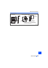
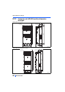
Installation size Installation size is not compatible. (New mounting holes are required.)
Converter Built in for all capacities The converter unit (FR-CC2) is required.
DC reactor DC reactor (FR-HEL) is provided. Built in the converter unit (FR-CC2)