


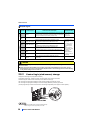
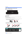
Control circuit
36
INSTALLATION AND WIRING
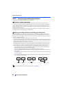
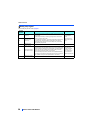
Safety stop signal
For the safety stop function, refer to page 45.
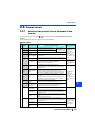
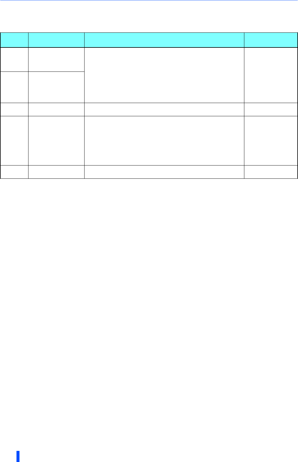
Terminal
Symbol
Terminal name Terminal function description Rate Specification
S1
Safety stop input
(Channel 1)
The terminals S1 and S2 are used for the safety stop input signal for the
safety relay module. The terminals S1 and S2 are used at the same time
(dual channel).
Inverter output is shutoff by shortening/opening between terminals S1
and SIC, or between S2 and SIC.
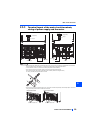
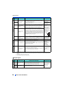
In the initial status, terminal S1 and S2 are shorted with the terminal PC
by shorting wires. The terminal SIC is shorted with the terminal SD.
Remove the shorting wires and connect the safety relay module when
using the safety stop function.
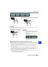
Input resistance
4.7 k
Input current 4 to 6
mADC (with 24 VDC
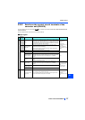
input)S2
Safety stop input
(Channel 2)
SIC
Safety stop input
terminal common
Common terminal for terminals S1 and S2. ———
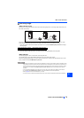
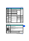
SO
Safety monitor output
Open collector output
Indicates the safety stop input signal status.
Switched to LOW when the status is other than the internal safety circuit
failure. Switched to HIGH during the internal safety circuit failure status.
LOW is when the open collector output transistor is ON (conducted).
HIGH is when the transistor is OFF (not conducted).
Refer to the Safety stop function instruction manual (BCNA23228-001)
when the signal is switched to HIGH while both terminals S1 and S2 are
open. (Please contact your sales representative for the manual.)
permissible load
24 VDC (27 VDC at
maximum), 0.1 A
(The voltage drop is
3.4 V at maximum
while the signal is ON.)
SOC
Safety monitor output
terminal common
Common terminal for terminal SO. ———