


110
APPENDIX
Low Voltage Directive
We have self-confirmed our inverters as products compliant to the Low Voltage Directive (Conforming standard EN 61800-5-
1) and affix the CE marking on the inverters.
Outline of instructions
Do not use an earth leakage current breaker as an electric shock protector without connecting the equipment to the earth. Connect the
equipment to the earth (ground) securely.
Wire the earth terminal independently. (Do not connect two or more cables to one terminal.)
Use the cable sizes on page 30 under the following conditions.
Surrounding air temperature 40°C (104°F) maximum
If conditions are different from above, select appropriate wire according to EN60204 Appendix C TABLE 5.
Use a tinned (plating should not include zinc) crimping terminal to connect the earth (ground) cable. When tightening the screw, be careful not to
damage the threads.
For use as a product compliant with the Low Voltage Directive, use PVC cable whose size is indicated on page 30.
Use the molded case circuit breaker and magnetic contactor which conform to the EN or IEC Standard.
DC current may flow from the inverter to a protective earth (ground) conductor. When using a residual current device (RDC) or residual current
monitor (RDM), connect a type B RCD or RCM to the power supply side.
Use the inverter under the conditions of overvoltage category II (usable regardless of the earth (ground) condition of the power supply),
overvoltage category III (usable with the earthed-neutral system power supply, 400 V class only) and pollution degree 2 or lower specified in
IEC664.
To use the inverter under the conditions of pollution degree 2, install it in the enclosure of IP2X or higher.
To use the inverter under the conditions of pollution degree 3, install it in the enclosure of IP54 or higher.
On the input and output of the inverter and the converter unit, use cables of the type and size set forth in EN60204 Appendix C.
The operating capacity of the relay outputs (terminal symbols A1, B1, C1, A2, B2, C2) should be 30 VDC, 0.3 A. (Relay output has basic
isolation from the internal circuit of the inverter and the converter unit.)
Control circuit terminals on page 24 are safely isolated from the main circuit.
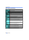
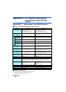
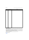
Environment (For the detail, refer to page 17.)
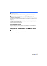
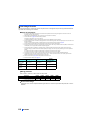
Wiring protection
Class T, Class J, Class CC, or Class L fuse must be provided.
Maximum allowable rating by US National Electrical Code. Exact size must be chosen for each installation.
Short circuit ratings
Suitable For Use in A Circuit Capable of Delivering Not More Than 100 kA rms Symmetrical Amperes, 550 V or 600 V
Maximum.
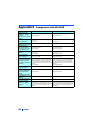
During operation In storage
During
Transportation
Surrounding air
temperature
-10 to +40°C -20 to +65°C -20 to +65°C
Ambient
humidity
95%RH or less 95%RH or less 95%RH or less
Maximum
altitude
2500 m 2500 m 10000 m
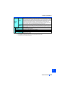
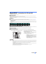
FR-CC2-[ ] H315K H355K H400K H450K H500K
Rated fuse voltage (V) 500 V or more
Fuse maximum allowable rating (A)
1100 1200 1350 1500 1800