Countermeasures against deterioration of the 400 V class motor insulation
72
PRECAUTIONS FOR USE OF THE INVERTER
NOTE
• Before wiring or inspection for a PM motor, confirm that the PM motor is stopped. In an application, such as fan and blower,
where the motor is driven by the load, a low-voltage manual contactor must be connected at the inverter's output side, and
wiring and inspection must be performed while the contactor is open. Otherwise you may get an electric shock.
• Do not open or close the contactor while the inverter is running (outputting).
3.5 Countermeasures against deterioration of
the 400 V class motor insulation
In the PWM type inverter, a surge voltage attributable to wiring constants is generated at the motor terminals. Especially in a
400 V class motor, the surge voltage may deteriorate the insulation. When the 400 V class motor is driven by the inverter,
consider the following countermeasures:
• Countermeasures
(With induction motor)
It is recommended to take one of the following countermeasures:
• Rectifying the motor insulation and limiting the PWM carrier frequency according to the wiring length
For the 400 V class motor, use an insulation-enhanced motor
.
Specifically,
- Order a "400 V class inverter-driven insulation-enhanced motor".
- For the dedicated motor such as the constant-torque motor and low-vibration motor, use an "inverter-driven dedicated
motor".
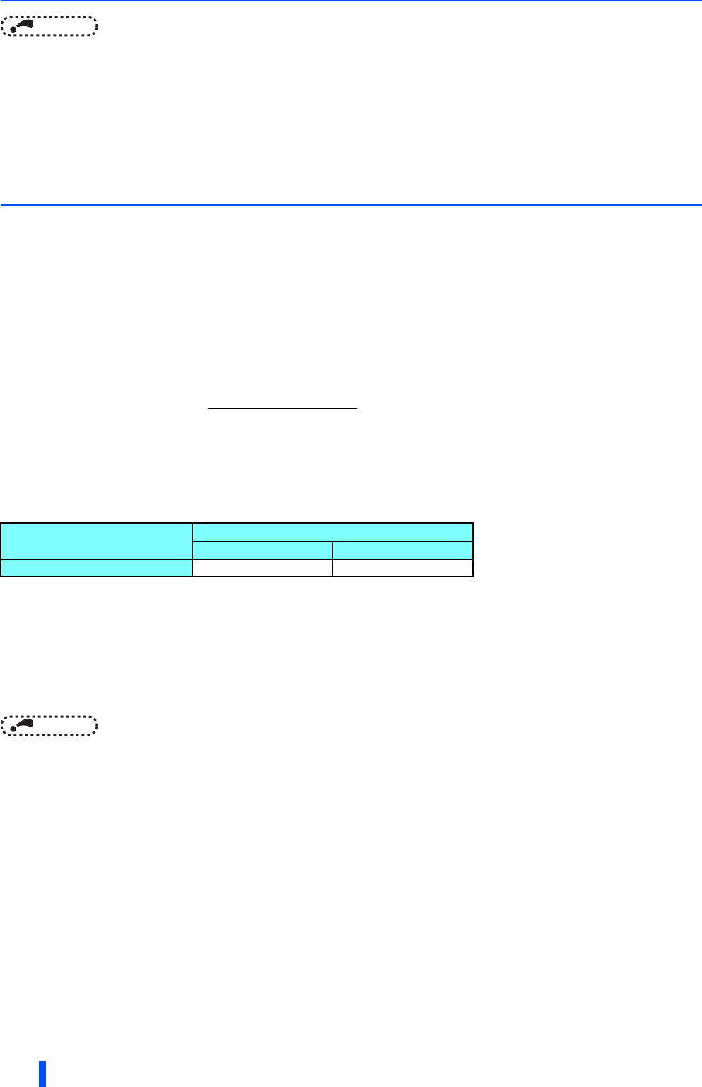
-Set Pr.72 PWM frequency selection as indicated below according to the wiring length.
• Suppressing the surge voltage on the inverter side
- If the motor capacity is 280 kW or lower, connect the sine wave filter (MT-BSL/BSC) to the output side.
(With PM motor)
• When the wiring length exceeds 50 m, set "9" (6 kHz) or less in Pr.72 PWM frequency selection.
NOTE
• When using the optional sine wave filter (MT-BSL/BSC), set Pr.72="25" (2.5 kHz).
• For the details of the sine wave filter (MT-BSL/BSC), refer to the Instruction Manual of each option.
• A sine wave filter (MT-BSL/BSC) can be used under V/F control. Do not use the filters under different control methods.
• The carrier frequency is limited during PM sensorless vector control. (Refer to the FR-A800 Instruction Manual (Detailed))
Wiring length
100 m or shorter Longer than 100 m
Pr.72 PWM frequency selection 6 (6 kHz) or lower 4 (4 kHz) or lower


